10.- Turn on/off a LED from the Internet. MQTT. Standalone.
- MQTT is a protocol used in IOT to control a device from the Internet.
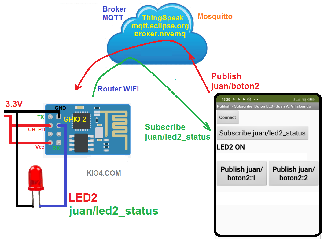
- In this example we will turn LED2 on/off from our mobile connected to the Internet. We can also check the status.
- For this you need a server on the internet, in the cloud, this server is called a Broker, there are many paid and free ones, we can also create our own on a Raspberry Pi with Mosquitto.
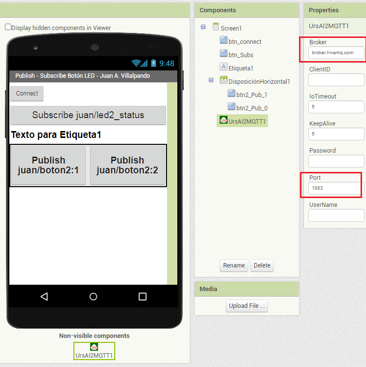
- In this example we will use the free broker broker.hivemq.com and port 1883, no registration is required.
- We will use the UrsAI2MQTT extension.
- Other MQTT examples:
https://community.appinventor.mit.edu/t/esp32-mqtt-broker-publish-subscribe-thingspeak/10490
p117B_ESP82666_mqtt_Extension_Btn_LED.aia (73.9 KB)
- Designer.
- Blocks.

- ESP8266-01. Code.
Summary
// http://kio4.com/arduino/57modulowifi_4.htm
// http://kio4.com/arduino/117_Wemos_MQTT.htm
// Juan A. Villalpando


#include <ESP8266WiFi.h> // Para el ESP8266
// #include <WiFi.h> // Para el ESP32
WiFiClient WIFI_CLIENT;
#include <PubSubClient.h>
PubSubClient MQTT_CLIENT;

const char* ssid = "Nombre_Red_WiFi";
const char* password = "Clave_WiFi";

#define LED2 2
String LED2_status = "-";

void setup() {
  pinMode(LED2, OUTPUT);
  Serial.begin(9600);
  delay(10);
  Serial.println();
  Serial.print("Connecting with ");
  Serial.println(ssid);

  WiFi.begin(ssid, password);

while (WiFi.status() != WL_CONNECTED) {
delay(500);
Serial.print(".");
}

Serial.println("");
Serial.print("WiFi conected. IP: ");
Serial.println(WiFi.localIP());

// Setting Callback.
  MQTT_CLIENT.setCallback(callback);
}

// What to do when it receives the data.
void callback(char* recibido, byte* payload, unsigned int length) {
  Serial.print("Message received: ");
  Serial.print(recibido);
  Serial.print("   ");

  for (int i=0;i<length;i++) {
    char receivedChar = (char)payload[i];
    Serial.println(receivedChar);
  if (receivedChar == '1') {digitalWrite(LED2, HIGH);}
  if (receivedChar == '2') {digitalWrite(LED2, LOW);}

    if (digitalRead(LED2) == HIGH) {LED2_status = "LED2 ON";} else {LED2_status = "LED2 OFF";}
  }
}

void loop() {
  if (!MQTT_CLIENT.connected()) {
    reconnect();
  }

  // PUBLISH topic.
// Convierte el entero a char. Debe ser char.
char led2_st[10];
LED2_status.toCharArray(led2_st, 10);

MQTT_CLIENT.publish("juan/led2_status", led2_st);
  delay(1000);
MQTT_CLIENT.loop(); // Check Subscription.

}

// Reconecta con MQTT broker
void reconnect() {
MQTT_CLIENT.setServer("broker.hivemq.com", 1883);
//MQTT_CLIENT.setServer("mqtt.eclipse.org", 1883);
MQTT_CLIENT.setClient(WIFI_CLIENT);

// Trying connect with broker.
while (!MQTT_CLIENT.connected()) {
Serial.println("Trying to connect with Broker MQTT.");
MQTT_CLIENT.subscribe("juan/boton2"); // HERE SUBSCRIBE.

// Wait to try to reconnect again...
delay(3000);
}

Serial.println("Conectado a MQTT.");
}
-
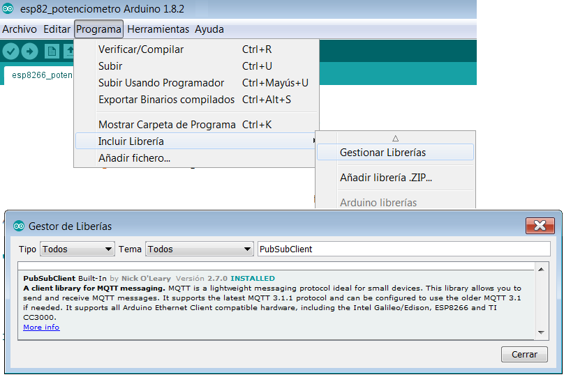
The <PubSubClient.h> library is required.
-
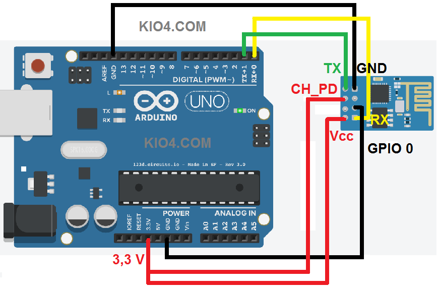
To load the Sketch in the ESP8266-01 we will use the Arduino and this connection...
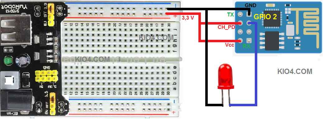
-
Then we can remove the Arduino and connect the LED to GPIO 2.