Subject: Request for Assistance – Accessibility App Project with MIT App Inventor (App Inventor controlled electric wheel chair)

Dear @hasanacar,
apart of the high current needed to drive your motors (to this purpose I suppose you're using the 50A motor drivers: how do you drive them, via PWM ? Don't they whistle when you raise up the speed ?) how do you intend to manage the direction ?
I mean: I suppose you have one motor each wheel (one motor on the Right wheel and another on the Left wheel), therefore to control Righ/Left you'd probably have to power supply only one while keeping steady the other and, to control the direction (back and forward) you'd reverse the polarity of the command to both ? Agreed that with the Hall effect you can control the speed and by its integral you can estimate the distance,where do you put the pick-up ? One for each wheel ? Are your wheels like those of bycicles ? (or you measure the distance and the speed is its time derivative ?) If you have two hall sensors, one for each wheel, you shall carefully perform the arithmetic average and implement a strong filter to avoid the loss of (or unwanted) pulses.
Since in your picture you have designed a flat-circled-type-joystick, have we to suppose the also the diagonal directions shall be managed as well ? For example if you push @45° right-up the dial, you'd like to go forward+right @45° ? This means that probably the easiest solution can be to send via BT to your Arduino the amount in degrees (i.e. 45°) and then it's a task of your Arduino to make the vectorial composition of the movement, by driving the left wheel with a higher voltage with respect to the right one, to obtain a 45° right and forward movement.
Most probably at a first step you should "survive" with a two step movement: 1st step to rotate a bit on the right the chair, then, 2nd step to go forward. When you will be done with that basic movement you will improve the movements with the
diagonal ones.

In a third step you could also add an ultrasonic sensor to your chair, in order to avoid to bump some furniture (and your wife's scolding :rofl:). and with the aid of this sensor and a map of your apartment you could also automate some basic movement within it (the apartment). More ideas to come...

In any case, you can search the forum for topics related to the driving of robot cars via AI2.
There are also tutorials on the matter (BT communication, motors drivers, joysticks, etc) on the web sites of some Power Users like @ChrisWard, @Juan_Antonio, @TIMAI2, @Taifun, and many others.

Lastly (for now): I see that you use the HC05 to perform the BT communication: this is fairly the best solution (with respect to BLE) because it's much simpler and you'll find many topics on that.
My hint is to start with a super simple app with the unique task to have a strong BT communication, i.e. to be capable to quickly resume after a power failure or after a disconnection (search the forum with the tag "handshake"). In case of long lasting disconnection your chair must go into a limp-home condition, or to stop immediately. To this purpose attached to the handshcke it would be good to have also the watchdog on Arduino, enabled.

(really ..)Last: just be careful to the Android version of your phone, or Android tablet, because the latest versions of Android are appllying almost daily, higher and higher restrictions to the use of interfaces. Therefore if you plan to use a specific device, be careful to block any Operating System automatic upfdate, otherwise you could run the risk to have a working app that suddenly stops working after a system update ... :rage:

Best wishes and feel free to ask further (i'll be abroad the whole next week but later I'll be back, hopefully).
Cheers.

2 Likes

Dear uskiara

Thank you so much for your detailed and thoughtful feedback.

Yes, I’m using 2 powerful 50A motor drivers, and I control them with 0–5V analog signals generated via an MCP4728 DAC module (no PWM, no whistling sound at all).
For direction control, I'm using relays to reverse polarity separately for the left and right motors (each connected to one wheel).

For now, I plan to install a Hall sensor on only one wheel to measure speed and distance. The wheel is bicycle-style, with a small magnet attached directly to it.

You're absolutely right about joystick behavior: I’ve already implemented differential drive using X-Y analog values. Diagonal directions like 45° forward-right work well by adjusting motor voltages accordingly.

At this point, I don’t need obstacle detection, watchdogs, or indoor mapping. But your suggestions are very inspiring and I may explore them in the future.

However, one critical feature I will implement — thanks to your advice — is a Bluetooth heartbeat mechanism. If connection is lost, the motors will immediately stop and brakes will be applied for safety.


Now, if I may add one very important and heartfelt request:

I kindly, sincerely and deeply ask for your help on this:
I have complete control over my system and hardware. Everything works beautifully.
The only thing I desperately need is a working .aia file to control my system via Bluetooth from my phone.
Please, I ask you from the bottom of my heart — could someone help me by creating or sharing such a file?
It would truly mean the world to me and complete my project.

Thank you again for your time, knowledge, and support.
I will keep the topic updated once Bluetooth control is fully functional.

Best regards,
Hasan Acar

More specific advice would require settling on message formats.

1 Like

Dear @hasanacar,
in the next two hours I'll take the flight for my trip abroad and for the next week I'll don't have the possibility to follow the forum, anyway, as you've seen, many other power users can give you help in the meanwhile. Not only, by digging the forum you'll find a lot of posts about joystick management. And don't forget to give a sight to the other PU's web sites. They are really a mine of information.
First of all, make the simple BT comm's between your Android device and the HC05 and rememeber to reverse the pins Rx to Tx and visa versa between Arduino board and HC05.
@ABG has already posted a link where you can find samples on that.
Best wishes,
Ugo.

1 Like

Hello everyone,

I had previously asked for help on this topic and received some useful suggestions. I truly appreciate all the support so far :pray:

However, I couldn’t make the system fully work because my knowledge of software development is limited.

I’d like to add something important: I am a person with physical disabilities, and I am developing this project not as a hobby but as a real necessity for my personal electric mobility device. This is not a luxury for me — it’s a real daily need.

My hardware is mostly complete. I can control the motors via Arduino using a joystick.
What I now need is a Bluetooth-based Android app made with MIT App Inventor that can:

  • Provide a draggable joystick in the center of the screen
  • Communicate with Arduino via HC-05 module
  • Display real-time data such as:
    • Battery voltage
    • Current speed (km/h)
    • Total distance traveled (kilometers)
  • Include a button to reset the trip counter
  • Allow the user to select Bluetooth device and connect/disconnect

I’ve tried exploring MIT App Inventor projects and forums, but I couldn’t create a working system on my own.

If anyone has a working .AIA file or is able to help me build such a system, I’d be incredibly grateful.
I am even willing to pay for the support, if necessary.

This project is not for fun — it’s for real-world, personal use.

I’ve also attached a sample mockup image of the interface to show what I’m trying to achieve:
:link: https://drive.google.com/file/d/1G9m9IlJMx0TlipGUCqc7Fxt_MI5kcXTn/view?usp=drive_link

Thank you so much to anyone who can help :pray:

Hasan A.

Ways you might control the wheel chair 'robot':

JOYSTICKS with aia code

Simple joystick.

The above is what you say you want. The code is not finished. Experiment.

Robot

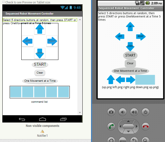
RobotControl.aia (6.1 KB)
This joystick can be used for initial testing. It can be used to test one command at a time or to set up a sequence of commands. This might be appropriate since you are For direction control, I'm using relays to reverse polarity separately for the left and right motors (each connected to one wheel).

VOICE CONTROL

Try the joysticks aia s out and find out for yourself if one method is what you want. :thinking:

OTHER STUFF OF POSSIBLE INTEREST

Possible Bluetooth sketch

2 Likes

Dear @hasanacar ,
any news about your project ? Did you succeed to make the BT comm's ?
Or the joystick section as per @SteveJG example ?
Kind regards.

1 Like

Dear @uskiara,

First of all, thank you very much for your kind interest and support.

I have designed a user interface for the mobile app I would like to use with my mobility system. You can see the layout mockup here:

In this layout:

  • The battery voltage gauge is on the left,
  • The speed display is in the center,
  • The total distance (odometer) is on the right,
  • There is a Bluetooth ON/OFF switch at the top,
  • And a "Reset Trip" button at the bottom.

Previously, I had planned to create a joystick-based interface, but it turned out to be too complex for my current skill level, so I gave up on that idea. This new layout is much more suitable for my needs, and I would be very happy if you could help me create it.

My goal is to connect the interface to an HC-05 Bluetooth module and receive data such as battery voltage, speed, and distance, as well as control a few functions via buttons.

I have searched through many forums and tutorials, but unfortunately, I don’t have enough experience in programming and app development to build this myself.

If you could create an .aia file based on this layout, it would mean a lot to me.

Thank you very much in advance for your time and assistance.

Best regards,
Hasan Acar

Dear @hasanacar,
i'll be truly pleased to help you, but I need to ask you to be a bit patient because my free time is really a little (though I'm retired, I'm managing many activities ... :fearful:).
Then we have to start from a working BT between the phone and the HC05.
(Honestly the layout that you have described does not match the image.png, but this is irrelevant for the time being :grin:)
So, the first .aia that I'll try to send you will be the one that implements the BT comm's. In the meanwhile, you can download from the Google playstore the SerialBluetooth Terminal app (free) that will help in verifying the operation of the communication without the need of your own developed app (i.e. to verify the HC05 side).
Firts of all, please let me know the exact HW configuration that you have: I mean which Arduino board do you have, and to which pins of the board you have attached the pins of the HC05. With this information I'll be in degree to write also an Arduino code matching the .aia.
Another important info is the Android level (unfortunately the most recent ones have increased the restrictions to the app's permissions),

Sooner or later (depending on Murphy's laws and my little time !) we'll get it working :muscle:
Ciao !

1 Like

Dear @uskiara,

First of all, I want to express my deepest gratitude to you from the bottom of my heart. :heart:
As a disabled individual working to build my own assistive system, your warm approach, your valuable time, and your sincere willingness to help mean a great deal to me.

Receiving such genuine support from someone I’ve never met on a forum makes me feel truly respected, valued, and not alone.
Every response and suggestion you share brings me real happiness.
Please know that I will never forget you. :star2:
You’re not only helping me with code and hardware — you’re giving me hope and motivation.
For that, I sincerely offer you my love and gratitude. Thank you again and again :pray:


:wrench: My current hardware configuration:

:green_circle: Arduino board: Arduino Uno R4 WiFi
:blue_square: Bluetooth module: HC-05
:iphone: Android version: Android 11

:electric_plug: HC-05 Connections:

  • HC-05 VCC → Arduino 5V
  • HC-05 GND → Arduino GND
  • HC-05 TX → Arduino RX (Pin 0)
  • HC-05 RX → Arduino TX (Pin 1)

:warning: To protect the RX pin (which expects 3.3V), I’m using a voltage divider made of two resistors to reduce the 5V signal.


:battery: Additional sensors and their purposes:

  • A voltage sensor module is used to measure the battery voltage. This value will be sent via Bluetooth and shown on the mobile app in real time.

  • A KY-003 Hall effect sensor is placed near a ring-type neodymium magnet attached to the wheel.
    Each time the magnet passes, the sensor detects it — allowing the system to:

    • calculate current speed (km/h)
    • track total distance traveled (km)

:framed_picture: For a better idea of the panel and how the system looks, here is a photo of the actual setup:
→ View Image


:iphone: Mobile App Purpose:

The system originally included joystick control, but I have now intentionally removed the joystick feature.
The mobile app will now serve only as a display/dashboard for real-time sensor data.

The app will not send any movement commands to the Arduino.
Its role is only to receive and display the following information:

  • :battery: Battery Voltage (in volts)
  • :biking_man: Current Speed (in km/h)
  • :straight_ruler: Total Distance Traveled (in km)

:white_check_mark: In addition, there will be a "Reset Distance" button next to the odometer.
When the user presses this button, the app will send a command to the Arduino via Bluetooth, which will reset the distance counter to zero.


Thank you in advance for the .aia file you’ll prepare whenever your time allows.
There is absolutely no rush — whenever you find a moment, it will be a true gift for me.

With love and appreciation,
– Hasan

Dear Hasan,
please don't thank me so much, because I didn't do anything, yet :grin:

As far as the HW connection of the HC05 is concerned it seems to me that it is pretty good (you took also care of the resistor partition to save the 3.3. vdc working voltage of the BT shield). Unfortunately I don't have in my drawers an Arduino UNO R4 WiFi so to have the same as yours, but a simple UNO with a HC05. Anyway I guess the code I'll write will work also for you.

Before starting, just a hint: since you have tied the R4 pins 0 and1 to the HC05, you'll not be allowed to use the Serial Monitor of the R4 in parallel, therefore it will be more difficult to debug the code.
In addition to this ,the pins 0,1 are used also to download the code from the PC to the board, so every time you want to reprogram the R4, you shall remove the pin 0 connection, otherwise the port will not work.

Therefore I strongly suggest you to move the connection to other pins, for example 10 and 11 and to use the SoftwareSerial library that allows to use other pins (like 2,3 or 10,11) thus freeing pins 0,1.

The ino code that you find annexed will allow you to find which is the baudrate of the HC05.

So, first of all, move the connection from pin 0 to pin 10 and from pin 1 to pin 11.

Go to the BT settings of your phone and select the option "find a new device": after a while the HC05 should appear in the list of found devices.
Select and pair it, typically with a pairing code like 1234 or 0000.

Start the SerialBluetoothTerminal app (SBT), and goto the menu Devices (the three horizontal bars on the top left of the SBT screen). The list of all the BT devices in the range will be shown: select the HC05 (for the rest of the project please write down on a paper the IP address that is shown below the HC05 name).
Once selected the HC05, return to the main screen of SBT and tap on the icon of the two connectors (on the top right corner of the screen near the trash can icon).
The SBT should write "Connected" after a while.
At that moment the HC05 shield should change the frequency of the red led blinking from fast to slow
(i.e. depending on the model, it could blink twice every 5 seconds).
Once you are done with that, do compile and download the annexed .ino to your R4 board. Set the Monitor baudrate to 9600 and run the code.
On the phone screen you shall see "unprintable" characters until the correct baudrate is found. When it is found, on the phone screen you will see the string "the baudrate is nnnnnn" where nnnnn is the baudrate number.
BaudRateDetect.ino (1.0 KB)
For tonite is enough (for me :sleeping:).
Ciao, ugo.

EDIT: the code has been compiled for a UNO R3 board so, before compiling it, you shall select the R4 board in your IDE. My IDE is rev 2.3.4 but any previous version should compile anyway.

2 Likes

Hi Ugo,

Thank you again for your help and your detailed suggestions.

I followed your advice and switched from pins 0/1 to pins 2 and 3 using SoftwareSerial. I also tested your baudrate detection code — it worked very well. I found that my HC-05 was operating at 38400 baud in AT mode.

However, after a few successful tests, the module suddenly stopped responding to AT commands, and it no longer sends readable data to the phone. I suspect the RX pin might have been damaged due to a mistakenly reversed resistor divider in the beginning.

So I ordered a new HC-05 module (ZS-040 version, with AT button and full pinout). Once it arrives, I will repeat the tests and let you know the results.

I really appreciate that you helped even though you didn’t have the same board as mine (Uno R4 WiFi). It means a lot.

By the way, I also have another Arduino board: a Nano clone V3.0.
If that’s helpful, I can run tests on it or share details in case it matches something you have in your drawers.

Also, just to say it clearly — I really like you. You've been so helpful and kind, and I truly appreciate your energy and attitude :blush:

(P.S. I know you said “don’t thank me too much”, but your support already helped me a lot :smile:)

Thanks again for your time and support!

Best regards,
Hasan

Dear @hasan,
...still too many thanks :rofl: :rofl: :rofl:. Really, It's just my pleasure to help, if I'm capable :muscle: :muscle: :muscle:.

OK, we've not been so lucky at the first attempt, therefore we have to investigate a bit more on the HC05 type/status/health.

In effect the HC05 works normally at 38400 but when it is in AT mode, when it works in transmission mode it works at 9600 or at 115200 (unless the user has actually programmed a different baudrate with an AT command). Only a few of them works also in transmission mode at 38400 (probably your one was such type of clone ?).

Please be aware that some HC05 clones have a different end-command characters: some have a CRLF pair (0x0D 0x0A) some others only the CR (0x0D).
If the HC05 is in command mode (i.e. AT mode) it does not transmit "normal" data, therefore you should not see any real BT transmission, but only a feedback to the command sender device.

The following pages (though referred to HC06 clones) could help.


Though it happens, honestly it's a bit weird that the HC05 has broken only after a short working time at a voltage higher than 3.3 (though < 5: even if you have reversed the resistors, the max VCC is 5 VDC, which typically does not damage the Rx pin so rapidly). In effect the resistors' partition isn't really 100% mandatory, but "advisory". The following image shows that connection.
HC06 Connection_3_3VDC.pdf (714.6 KB)

Another symptom of working status is the frequency of blinking: as soon as the HC05 powers on, it blinks rapidly until it is connected to a client, and depending upon a sequence of HIGH and LOW voltages to specific pins, it enters the command mode (AT) and blinks with a specific frequency (unfortunately it depends upon the clone manufacturer), and at the end, if it does not enter, or leaves, the AT mode,and goes into the transmisison mode, it changes to a slower one (or a steady one).

Therefore I suspect that the HC05 has entered an unknown mode (maybe it has entered the Master mode, in which it behaves as a client ( :rage:), and therefore it only needs a HW reset. How to do this probably you can try with the aid of one of the following datasheets.

HC-05 Datasheet.pdf (840.6 KB)
HC05 master-slave.pdf (1.5 MB)
HC05_AT_Commands.pdf (83.7 KB)

Another easy, at no cost, test is to change the R4 pins and see what happens.

Yes, I have some NANO, MEGA, ESP8266 and ESP32 boards, somewhere in my drawers, but the UNOR4 and the UNOR3 are, most probably, more similar each other than the other ones, so let's continue with the current configuration.

Another quick test is, connect your NANO following my drawing above, and see what happens.

A trivial doubt: since you've connected pins 2 and 3, instead of 10 and11 as per my Arduino code, I assume you've changed the Arduino source accordingly (sorry to bother you with trivial details, but ...never say never... :grin:).

When you've purchased the HC05, has its specific datasheet been supplied you, as well ? If so, can you share it me, please ?

Another hint is: when you feel in a blind alley, before crying too much and tear your hair out, you could have also a look to the web site of Chris Ward (professorcad.co.uk - @ChrisWard ) where you can find ton's of examples and explanations about Arduino and Bluetooth.

Anyway, since you've already purchased a new HC05, as soon as it arrives, please let me updated.

For sure we'll never give up !
Ugo.

1 Like

Today I've had a half day-off so I've developed the following .aia and .ino.
Once you're done with the HC05 troubles, (very useful and clear link here below)

you can install the app on your phone and the .ino on your R4 (You already know that I've developed on a UNO R3 but, in a nutshell, it should work either).
The app's graphical layout is a bit raw, but it can be the structure of a more sofisticated one (please be aware that I use a 8" tablet instead of a phone, therefore the screen ratios are slightly different).
The app+ino codes implement the BT communication and the handshake method in case of failure. The ino sends periodically (each 500 ms) a fake odo, speed and battery dataset to the app, that shows them on the screen. The app sends A,B C (simulated commands) when their respective command buttons are hit.
HIDE/SHOW screen is intended to reduce phone's battery consumption because the screen is just darkened but the app is still running.
BRIGHT +/- can work only if the app can be allowed to modify system behaviour (by means of app's permissions at Android level) .
In the screen area above the ODO display, there are two debug rows displaying the BT traffic between Arduino and the app. At the end of the development they can be hidden.
In the code I also use two @Taifun 's ( :hugs::+1:) extensions: one to allow the app to stay always awake, and the second to read the phone's battery charge level and status.

NOTE: if, at the first start, Android asks you to allow BT communication and Geolocalization permissions, you must allow both, otherwise the BT will not work.
If they are not asked, please enter anyway the app's permissions menu (in Android) and check if both are set. If not, please allow both. This shall be done only at the first installation of the app; at any updates it will not be necessary :disappointed_relieved:
Apart of permissions, please remember that the BT does not work if the BT and Geoloc are not set every time you'll use the app.

ChairCommander.ino (6.6 KB)
BT_Chair_Commander.aia (1.8 MB)

1 Like

Dear Ugo,

I’m truly grateful for the time you took and the attention you gave me. Whether it’s directly related to my project or not, your support means a lot to me. I have deep respect for you and I sincerely appreciate and love you. Thank you so much for all the knowledge and effort you shared.

Once my Bluetooth module arrives, I will share the results with you—no matter if it works or not. I won’t forget your support.

Thank you once again. :pray:

With warm regards,
Hasan

1 Like

Dear Hasan,
I forgot to say somethig about the app.
I use the following naming conventions:
Labels start with L_
Buttons start with B_
Clocks starts with Ck_ (or Clock_ )
Sliders start with SL_
Spinners start with SP_
...and so on.

I also collapse all the "functional blocks" so to save the PC screen area, to toggle beteween the collapsed/uncollapsed sight just double click on them.

For example, this is the area of Buttons' events:
image

This is the procedures area:
image

Variables are collected close each others according to their type (numbers, texts, lists, booleans)
image

The BT address thay you see in my aia shall be substituted by your "new" hc05 one:
image

The screen layout looks like this:


which is not as per your image, but I've started from an already made and I've just modified it
Up to now, it is running since three/four hours without any BT interruption, therefore it seems sufficiently "robust". But we have to see at the end, when the sensors' management Arduino code willl be implemented and run, as well.

One question: how do you manage the speed and odometer data ?
In other words, how (and where) do you compute them ? On the R4 itself ?
If yes, the Hall sensors are digital, i.e. their signals are ON/OFF, or analogue ?
Because if they have to be handled by the R4, we shall read them by means of one or two Interrupt lines.
Anyway: let's do one step at a time. Let's see if the BT works as we expect with the incoming HC05, but do not throw away the current one: please take a look at the tutorial that I've linked in my previous post: most probably, and hopefully, it has only entered a "strange" mode of working and it's not broken. Many clones have really weird behaviours.
Have a great weekend.
Ciao, ugo.

PS I forgot also that there is also another extenison, by @Anke ( :+1:) that I've used to modify the standard fonts into a seven segment font. Vielen Danken !

1 Like

Dear Ugo,

Thank you very much for your detailed explanations and for sharing your naming conventions. This kind of approach really brings a professional and sustainable quality to the project. I truly owe you a lot.

As for your question:
Yes, I’m doing the speed and distance calculations directly on the Arduino R4. I’m currently using a single A3144 Hall sensor, which gives a digital output (LOW–HIGH signal). The sensor is connected to an interrupt pin on the Arduino. Every time the magnet passes by, it triggers a pulse, and by counting these pulses, both the instantaneous speed and total distance (in kilometers) can be calculated.

I’ve measured the total circumference of the wheel: it is 1.30 cm.
So, each sensor pulse corresponds to approximately 1.30 cm of movement.
This allows me to calculate the traveled distance very precisely.

The calculations are done every 500 ms on the Arduino, and the values for AKU (battery), HIZ (speed), and KM (distance) are sent via serial to the App Inventor app. Currently, I’m using simulated values for testing, but the system is fully ready to work with real sensor data.

Once my HC-05 Bluetooth module arrives, the first thing I’ll do is configure it with AT commands, just as you suggested. Then I’ll update the app with the correct address and run some tests. Whatever the result, I’ll definitely share it with you.

Thank you once again. Your time, your guidance, and your support truly mean a lot to me.
With love and respect,
Hasan

Dear Hasan, as far as I can read you've already done a great job on Arduino.
So what you'll need to do is to add (integrate) my BT code to yours.

Just a little comment: I believe that your wheel circumference is 1.30 meters (and not cm :rofl:).

Since you talk about speed and Kilometers, this means that are you using your wheelchair outside ? on streets ? Please be careful !!! If you were here in Italy you should write down your will (to leave your inheritage :fearful:!) before going through roads....

Anyway, though I could respond with some delay, please do not hesitate to write me at any time.
Buona serata.
Ciao, ugo.

1 Like

Dear Ugo,

First of all, thank you very much for your kind words. I’ve made real progress on the Arduino side — and that’s largely thanks to your support. I’ll integrate your BT code into mine, and now I feel more confident doing that.

As for the wheel circumference — yes, let’s call it a little "unit error" :sweat_smile:
It’s actually 1.30 meters, but in my excitement I wrote “cm”. If I were in Italy, I’d probably have to write my will before even heading out the door! :smile:

Jokes aside, I do plan to use my system outdoors, so safety and reliability are top priorities for me. Every piece of advice you give is truly valuable.

Even if your replies come with some delay, I always wait patiently and gratefully.
Thank you again — have a great evening!

Warm regards,
Hasan

Absolutely true: we are the birthsite of Ferrari, Maserati, Lamborghini, Ducati....and much more.... :rofl: :rofl: :rofl:

Jokes aside, I do plan to use my system outdoors, so safety and reliability are top priorities for me. Every piece of advice you give is truly valuable

When you'll feel comfortable and confident with the app, and you'll want to implement the joystick on the phone, it will become mandatory to make absolutely "strong" the communication and to implement an immediate safe-stop-wheels algorithm.
But this is another story.
Buonanotte !