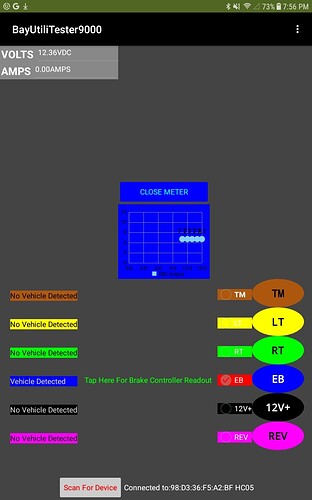
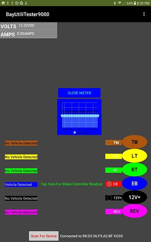
I almost have my app just the way I want it but I have no idea how to go about this last finishing touch. I've attached my aia file to see what I'm talking about, the left side is where my vehicle connector data gets expressed .
With the exception of the blue circuit, all I need to know is whether or not there is voltage on the circuit. As far as I'm concerned, they're either on or off...
But the blue circuit is receiving it's input from an electric trailer brake controller in the vehicle that gives out a variable voltage depending on how aggressively it's going to operate the trailer's brakes. That's the only circuit that I might need to know how much voltage is on the circuit and see how quickly it changes with the position of the brake pedal so I can roughly tune the output of a newly installed brake controller.
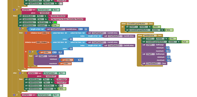
So I'm trying to make it so when that blue circuit goes active from vehicle input, the arduino will switch from sending on/off messages to sending a live voltage number and a scrolling graph pops up in that row that gives a live visual readout, sorta like how the volt and amp meters work but plotted out on a slow oscilloscope looking thing instead of a numerical readout if that makes sense...
I get the ominous feeling I'm opening up a can of worms and asking for something more complicated than I'm prepared to understand even if someone tried to spell it out for me... but I'll give it my all if anyone has the patience to try and help me with this, I would be so very grateful.
many thanks in advance for any assistance that can be offered with this. This community, particularly Patryk, has been so kind and generous with their knowledge and time. My project sat in stagnation for over a year until I discovered MIT AI and you guys have brought new life into it and progressed it in ways I only imagined when I first started building this thing.
BUT9KTOGGLE.aia (99.4 KB)


