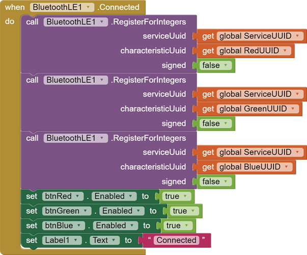
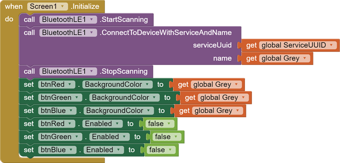
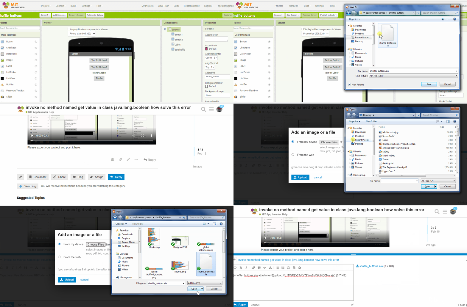
(Canned Reply: ABG- Export & Upload .aia)
Export your .aia file and upload it here.
Here are your new characteristice from your latest .aia export:
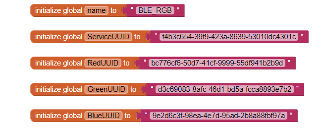
Now NONE of them match your sketch's UUIDs at
Maybe you should also post your new sketch too?
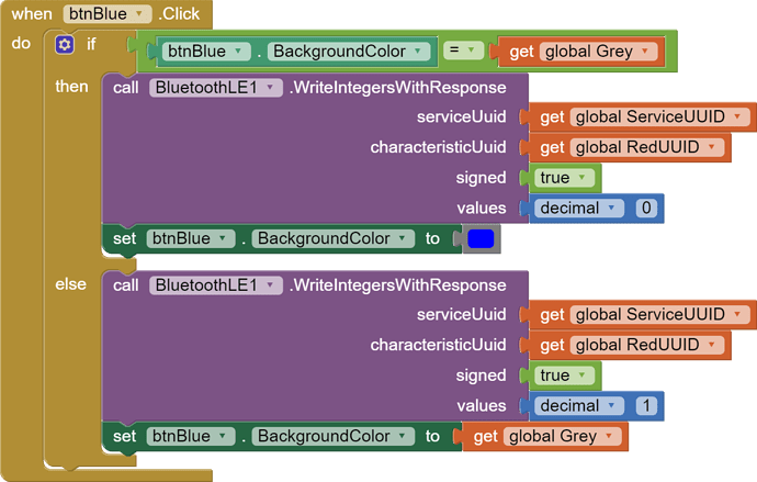
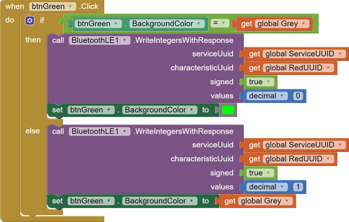
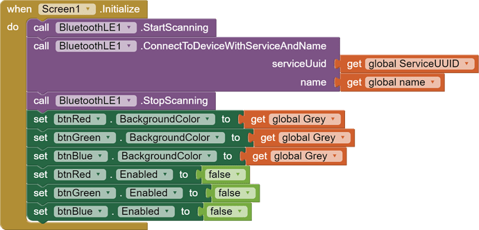
Also, I do not like the way you are using background color of buttons to remember their states.
The color blocks look too similar to the coder and might not be exact matches, block to block.
(I once got burned by this doing a Wordle app.)
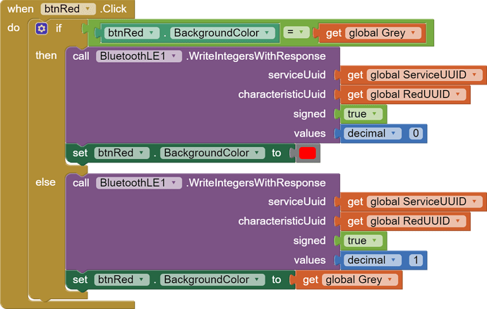
I renamed the three color buttons to help code readability.
Here is alternative code:

According to
you are missing a test of the characteristic value, like that '1' or '0' you are sending.
(I missed that code all the way to the right in the sketch. But do the data types (char vs int match?))
Also, is that any way to talk to an LED?
Your code, for the phone users:
XIAO 8-9-24 Sketch

include <ArduinoBLE.h>


// Theses are the BLE UUIDs
BLEService LEDService("f4b3c654-39f9-423a-8639-53010dc4301c");  //Service UUID hexadecimal numbers
BLEIntCharacteristic redCharacteristic("bc776cf6-50d7-41cf-9999-55df941b2b9d", BLERead | BLEWrite | BLENotify);
BLEIntCharacteristic greenCharacteristic("d3c69083-8afc-46d1-bd5a-fcca8893e7b2", BLERead | BLEWrite | BLENotify);
BLEIntCharacteristic blueCharacteristic("9e2d6c3f-98ea-4e7d-95ad-2b8a88fbf97a", BLERead | BLEWrite | BLENotify);

const int redPIN = LEDR;                            //pin to use for the red LED (D11)
const int greenPIN = LEDG;                          //pin to use for the green LED (D12)
const int bluePIN = LEDB;                           //pin to use for the red LED (D13)


void setup() {

  pinMode(redPIN, OUTPUT);                           //set pins as outputs and set LED's HiGH ( HIGH is off for this board)
  digitalWrite(redPIN, HIGH);
  pinMode(greenPIN, OUTPUT);
  digitalWrite(greenPIN, HIGH);
  pinMode(bluePIN, OUTPUT);
  digitalWrite(bluePIN, HIGH);

  if (!BLE.begin()) {                                      //  begin initialization
    while (1) ;                                              // wait until initialization is complete
  }

  BLE.setLocalName("BLE_RGB");                            // set advertised local name
  BLE.setAdvertisedService(LEDService);                   // set advertised service UUID
  LEDService.addCharacteristic(redCharacteristic);        // add the red characteristic to the service
  LEDService.addCharacteristic(greenCharacteristic);      // add the green characteristic to the service
  LEDService.addCharacteristic(blueCharacteristic);       // add the blue characteristic to the service
  BLE.addService(LEDService);                             // add service
  BLE.advertise();                                        // start advertising
}

void loop() {
  BLEDevice central = BLE.central();                      // listen for BLE devices to connect:  Not sure that this works for ESP32

  if (central) {                                          // if a central is connected to peripheral

                                                         // put code here to perform 1 time when device is connected

    while (central.connected()) {                        // While the central is still connected to peripheral

                                                         // if there is an update from the Android App, change light ON (0) or OFF (1)

      if (redCharacteristic.written()) digitalWrite(redPIN, redCharacteristic.value());
      if (greenCharacteristic.written()) digitalWrite(greenPIN, greenCharacteristic.value());
      if (blueCharacteristic.written()) digitalWrite(bluePIN, blueCharacteristic.value());

        }                                               // end of while loop

    }                                                   // you can put code here for what to do when not conected

}                                                       // end of loop
Thank you ABG,,I will confirm that this is the proper way to talk to LED via the XIAO examples.
I will get back with you.
Sorry, I applied the wrong global variable name in one block:
I notice you varies wildly from the Service UUID in your choice of characteristic UUIDs.
Why?
Could there be a requirement of some similarity between the device UUID and characteristic UUIDs?
I notice you are one version behind in your BLE extension version.
The newer version handles permissions better.
Apparently it is okay, according to the video.
Asides from the Characteristics and the button background color testing, I see nothing wrong.
Maybe try another board?
How's your USB line voltage?
Do red LEDs need less power than other color LEDs?
I will serch for other examples to control the LEDs. I want to be able to control I/O via Bluetooth and this XIAO example is great for my application.
I changed the board to a "Sense" board and I have changed to a different USB C cable and port. The results have not changed. Only the red LED comes on no matter which selection that I use on the app.
Surely, there must be other methods of controlling I/O via Bluethooth.
Thank you for all your help!
Did you notice the YouTube video has links to get the source code?
No hand copying needed, no opportunity to mistype something.
I have gone through all those links.. There is actually no code there.
I stopped there.
Great News!!
I downloaded the authors files and implemented them.
They actually worked!!
I get the all the proper color LEDs when I select the RED, GREEN, and BLUE buttons.
I am going to investigate to determine where I entered the snafu.
This has been a real battle. You have helped to understand several of my misteps!
AGB thank you for all your help!!
So, how much money was all our time worth?
$10...
I compared the two sets of sketches and code.
The sketch was perfect.
My problem was in the blocks.
I had declared each button's characteristicUuid as "get globalRedUUID". This is why the only the red LED would come on!!
Oh well, we live and learn. Again, I thank you for all your help.
This is a learning community indeed.
My takeaway is the importance of renaming buttons in the Designer to their purpose, like btnRed, btnBlue, btnGreen.
That would have exposed the mismatch in the blocks.
There is a comments section on the YouTube video, should you want to spread the word.
ABG, Thank you for this input. I will add my experience to the Youtube comments. Have a great day.
