Dear all,
since I was looking for a low pass filter with a simplified equation and I didn't find a "really simple one", I've searched in my rusty mind and I remembered what I was using to implement a generic low-pass filter when using microprocessors with poor mathematical capabilities.
Probably nobody will never have the need to use it, anyway, II've tried to put it in a (re)usable form.
This low-pass filter is not the typical RC filter used in electronics, but a generic one, that can be used to smooth down any type of input affected by ripple or by sudden spikes.
I've seen that there are other topics related to low-pass filters, but I think that the advantage of this implementation is that it uses just the sampling time and the time constant to generate the two gains used into the equation.
I've taken this opportunity also to play with the nice extension from @Juan_Antonio to draw dynamic graphs and the (always present ![]() ) @Taifun for his keep alive screen and @Ken for his TextBoxTools extension.
) @Taifun for his keep alive screen and @Ken for his TextBoxTools extension.
Here below the .aia and a "one page document" to explain (without mathematics details because, I believe, out of the scope) the algorithm.
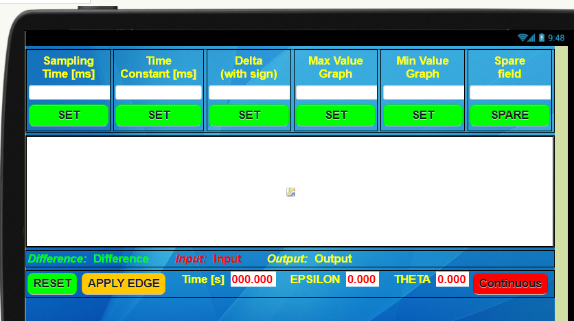
The main (unique) screen shows the sampling time, the time constant, the edge value (delta), the min and max values of the graph.You can play with the values so to see the different responses of the filter when hitting on the "Apply Edge" button. The "Time" output shows the seconds that the filter needs to asymptotically reach the 10% of the final value (i.e. the edge). The counter stops when this value is reached.
I've used this type of filter to smooth down the inputs coming from an Arduino board interfacing analogue Hall sensors to count the RPM of a car wheel(s).and it works.
As I said , most probably no one will never need it, but in the case .... ![]()
Ciao ciao.
Low_Pass_Filter.aia (123.0 KB)
Block Diagram.pdf (59.5 KB)