Universal Simulator. Something that doesn't exist, and it is a must in the electronic industry.
Thank you to all who read this thread and all who helped and will help on this thread.
I know, that sometimes a good idea can have value more than 1000 hours of bad work.
@TIMAI2 came up with what seems to be one of the best ideas about my project...
Thank you TIMAI2 for the kind words and for that idea.
Here it somehow must be the second default screen without active cells. The first screen will be a start screen with the logo and conditions the users/technicians, must accept every time they want to work with the tool.
For the machines I have now, a 3K/13" tablet and a 4K/27" touchscreen monitor, will be 2 variants of that screen, adapted to each resolution. A resizable screen is not a bad idea. I don't know if a resizable screen or two versions of the app, for that two displays is best as an approach.

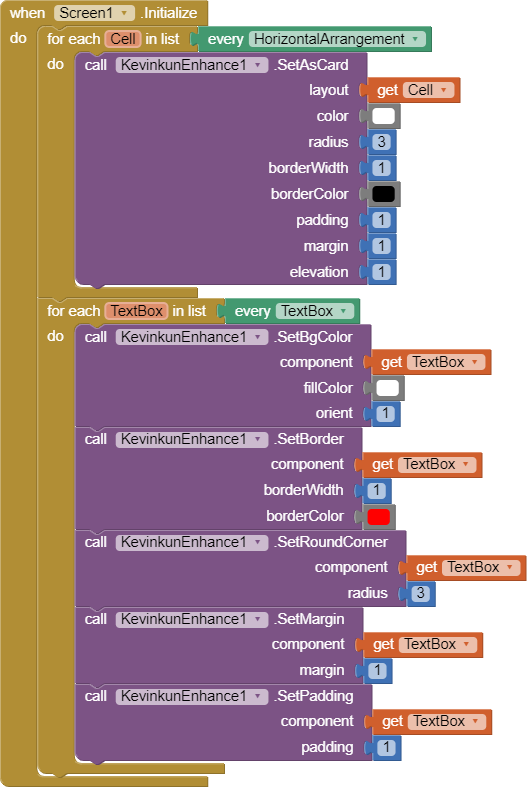
As you can see on this thread above, TIMAI2 already made a .aia from a didactical point of view that guided me to make another .aia. If I can make this, for a real professional in AI2 that can be an easy task.
In continuation, I will give you some general details about this screen.
Logo - is the logo of the system.
Header large rectangle, next to the logo. It will receive from the online website the actual problems, that users who work with the system encounter and are searching for an answer. Making a click on the four puzzle pieces will take them to the problem that needs help.
In continuation of the header, there are two buttons for quick access, the first/top to a menu, the second/bottom a button as quick access at a functions menu (erase ECUs errors and so on...).
In continuation of the header, it is the next rectangle that informs about what kind of electronic module it has in the working process and the QR code will inform about the stage/history of that module.
In continuation of the header, there are a few rectangles that inform the technician about the power supply parameters for that module.
The 128 cells, short explanation.
Here is all the logic behind the universal simulator. A cell has a number- the red rectangle with the number inside. That cell number never changes. It is static and defines the ID of a cell on software and, at the same time, defines the cell number in hardware. It has this order because the hardware part of the simulator will be with the cell number one closest to the technician.
So... The cell number defines the place in the software and hardware of a... Wire. or a wires (more than one wire - ex: CAN-bus, ISO-bus, and so on, automation busses, two wires).
So... The scope of that universal simulator is to simulate/generate any electronic possible conditions needed in an electronics module pin, to work as it works in its original place where is used. Ex: ECU - Engine Control Unit, which is used to control engines from boats to airplanes, from cars to tractors, buses, trucks... and so on.
Without a universal simulator, for example, an ECU can't be started properly on the workbench, the technician is unable to erase the errors after repairing and the ECU can't be properly tested on the bench.
Any cell must have:
The red rectangle with the Cell-ID.
The blue rectangle with the code number of connectors where the wire/wires from that hardware cell go - is connected.
The green rectangle with the code/codes for pin/pins, where the wire/wires from the hardware cell go - is connected.
Thank you very much for your attention, I will continue this... "short" description of that project that is only a part of another project - iESN - International Electronic Service Network. For that project, I plan to use AI2 for almost all that is needed to make it work, if AI2 can do that.
It will be continued because there are details that must be considered from the starting point...