As the name says, how can I connect 100+ esp32 to AI2?! Wifi or Bluetooth? There are some limitations in the number of esp32 connected to AI2 over Bluetooth or wifi?!
Most of all, of these 100+ esp32 are sensors (I2C, SPI, and so on) or LED but some (3 to 5 pcs of that esp32) are CAN-bus and other buses.
All that can be connected directly to AI2 or must be used an intermediary access point?
How many webview instances are the maximum allowed? Must I use 100+ instances? Or must I combine in some manner before displaying those parameters?
I plan to create a screen with a matrix/array of 100+ cells. In that cels, I want to display the values. This is a particular tablet-related app, not a cell phone/universal app.
Further, I want to have the possibility to click in one cell and modify some parameters.
It will be some kind of complicated app, unfortunately, I can't make public the purpose of this app.
Yes, sir, this can be a good starting point. Bluetooth or wifi? I think wifi can be a good choice due to 150 Mbs. Must include an access point between 100+esp32 and tablet or not?
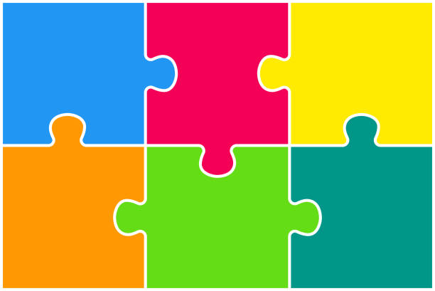
I have many questions here about how can it be made on this project, for example, how can I make this table look like somehow real (interlaced) puzzle pieces? I read tons of puzzle-related threads, but none answered this question.
Well... yes, this was the only solution that my intuition saw after I read all that I'd found about puzzles. My question is... It can be overlayed all that canvas?! Can I put them in whatever place on the screen?
With time ago... I read this... "In the next version ai2, nb187, it will be possible to freely arrange items on the screen and to move them. In my opinion, this will allow the components to overlap, and you will be able to decide which element should be on top. If you are interested in a label, you can use my extension which allows you to move the label to any place specified in pixels." here...
But I can't find these features or weren't implemented. Because I need to overlay some data on top of puzzle pieces.
You're right, what I have tested until now on Bluetooth was 3 X esp32 simultaneous, and it works great (Juan documents for settings up). But I think that 100+ will be a pain. On Bluetooth, the only way is to connect/disconnect all 100+ sequentially. On the wifi, I think that it can be always connected all 100+ esp32. This must be tested because until now... nobody has tested this approach (or I don't know found any info).
I'm sorry, I don't see it... This I want to be somehow interactive... let's say background or... in fact as AI2 works (AI2 was the real inspiration for this application). I will try to draw some parts of the screen to be more concrete.
You can load an image as a background in an Arrangement, and load the Arrangement with sub Arrangements full of other components.
By means of Generic (Any) blocks you can reuse components and relabel them.
Component blocks can be kept in global lists to correspond with their Arrangement locations.
All puzzle pieces are esp32 with different functions (colors). Blue will give variable voltage, green - variable temperature, orange on/off out... and so on. Until now I know about 20 functions but in the future will be more than that.
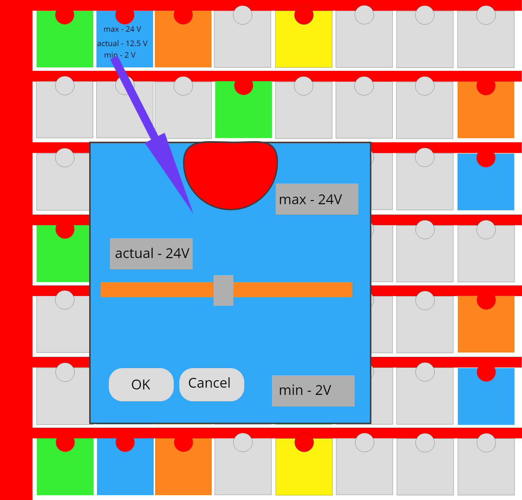
Normally all puzzle pieces are the same measures. When I touch eg: the blue one must appear (animated if I can) the big puzzle piece where I can modify, save, and organize the info from that puzzle piece.
The red marks represent the power supply for esp32 puzzle pieces. It will be a wireless power supply and will be somehow more complicated... It will have some references, some independent GND's, and so on.
The big blue square, it is for exemplifies a slider that modifies a voltage between some pre-established limits (I forgot to correct the actual voltage to 12.5V as is in the small blue puzzle piece).
Please forgive me, art is not my strong point.
Thank you, Dan
PS - @TIMAI2 good starting point for inspiration. Mathematics... oh no... not again. Can be arithmetic... only?!
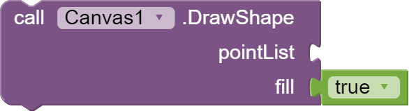
This looks like something that could be drawn on a Canvas, given value functions to turn rows and columns into px and py values at run time based on Canvas.Width and .Height.
The splash would be drawn after everything else, if a square was poked.
A fat line can be used to "erase" rectangles prior to redrawing text or fake sliders on it.
Thank you very much for your opinions and examples. They are always welcomed. What I'm trying to do is to see how I can give some nice design to the functionalities. I'm almost sure that I can create a simple interface based on arrangements (horizontal/vertical).
For the moment, I'm relying on intuition regarding what I want. I believe that AI2 can somehow assist with some minor design tasks.
Unfortunately a like I want app doesn't exist and I don't have from where I can inspired.
From what I see, and read about AI2, it seems that my purposes can be achieved with some vertical/horizontal arrangements, vertical/ horizontal arrangement background images to give some "puzzle pieces" shapes (I don't know if accept .png, I say .png due to transparent background), some plays with the visibilities of that arrangements, some canvas and canvas visibilities to activate/deactivate some connection graphics, on arrangements, I can place some text boxes/labels or sliders.
The parameters that came over wifi from 100+ of esp32I can be displayed in the text boxes/labels, and the parameters that I need to send over wifi I can send from labels/text boxes/sliders that already I have.