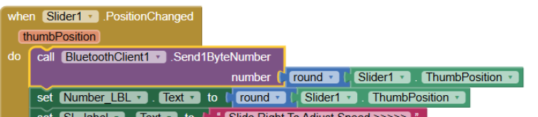
You can also add a 200ms repeating clock timer to compare a new global previous thumb value against the current thumb, and transmit only when the thumb has changed. Remove the transmit block from the thumb changed event.
Move it to the clock timer event block.
@ABG I am using arduino with Bluetooth module and sometimes BT module gets stuck (even I closed my phone BT, arduino BT LED still indicating a normal connection as connected while my BT is OFF )along with the slider app itself and the thumb freezes resulting in app not responding any idea how to send data in a more controlled way. Note: I have blocked some slider values so that I can use them for another button to control LED.
my code is here:
volatile bool mydelay   = false;
int myvalue             = 0;
uint8_t last_CH1_state  = 0;

const int PinDiac       = 3;
const int PinLed        = 11;

enum { LedOn = HIGH, LedOff = LOW };

// -----------------------------------------------------------------------------
void setup () {
  Serial.begin (9600);

  PCICR  |= (1 << PCIE0);    //enable PCMSK0 scan
  PCMSK0 |= (1 << PCINT0);  //Set pin D8 trigger an interrupt on state change. Input from optocoupler

  pinMode       (PinDiac, OUTPUT); //Define D3 as output for the DIAC pulse
  pinMode       (PinLed,  OUTPUT);
  digitalWrite  (PinDiac, HIGH);
  digitalWrite  (PinLed,  LedOff);
}

// -----------------------------------------------------------------------------
void loop () {
  if (Serial.available()) {
        char rec = Serial.read ();

        Serial.print ("  rec ");
        Serial.println (rec, DEC);
    switch (rec)  {
      case '\n':
        break;

      case 0:  // OR ANY VALUE SENT BY THE APP!!!
        digitalWrite (PinLed, LedOff);
        break;

      case 1:  // OR ANY VALUE SENT BY THE APP!!!
        digitalWrite (PinLed, LedOn);
        break;

      default:
        myvalue = map (rec, 0, 180, 6700, 10);  // OR ANY VALUE SENT BY THE APP!!!
        Serial.print   ("  myvalue ");
        Serial.println (myvalue);

        break;
    }
  }

  if (mydelay) {
    delayMicroseconds (myvalue); //This delay controls the power
    digitalWrite      (PinDiac, HIGH);
    delayMicroseconds (100);
    digitalWrite      (PinDiac, LOW);
    mydelay = false;
  }
}

// -----------------------------------------------------------------------------
ISR (PCINT0_vect) {
  uint8_t currentState = PINB & B00000001;
  if (currentState != last_CH1_state) {
    last_CH1_state = currentState;
    // if (currentState == B00000001) { // REMOVE THE IF TO TRIGGER THE PULSE ON BOTH EDGES
    mydelay = true;
    // }
  }
}
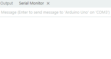
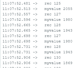
Serial monitor output
Why the slider is sending -128 and not 128
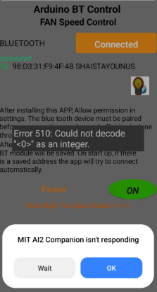
hi, I am trying to send text or a number via bluetooth to process it in arduino, but serial monitor doe not display anything. I am getting this error in my app.
int detectado            =  0;
int myvalue              =  0;
int last_CH1_state       =  0;
const int PinLed         = 11;
enum { LedOn             = HIGH, LedOff = LOW };
void setup() {
  /*
   * Port registers allow for lower-level and faster manipulation of the i/o pins of the microcontroller on an Arduino board.
   * The chips used on the Arduino board (the ATmega8 and ATmega168) have three ports:
     -B (digital pin 8 to 13)
     -C (analog input pins)
     -D (digital pins 0 to 7)
  //All Arduino (Atmega) digital pins are inputs when you begin...
  */

  PCICR |= (1 << PCIE0);    //enable PCMSK0 scan
  PCMSK0 |= (1 << PCINT0);  //Set pin D8 trigger an interrupt on state change. Input from optocoupler
  //pinMode       (PinDiac, OUTPUT); //Define D3 as output for the DIAC pulse
  pinMode       (PinLed,  OUTPUT);
  //digitalWrite  (PinDiac, HIGH);
  digitalWrite  (PinLed,  LedOff);
  pinMode       (3,OUTPUT);        //Define D3 as output for the DIAC pulse
  Serial.begin(9600);       //Start serial com with the BT module (RX and TX pins)
}

void loop() {
   //Read the value of the pot and map it from 10 to 10.000 us. AC frequency is 50Hz, so period is 20ms. We want to control the power
   //of each half period, so the maximum is 10ms or 10.000us. In my case I've maped it up to 7.200us since 10.000 was too much
   if(Serial.available())
   {
      myvalue = map(Serial.read(),0,255,6700,10);
      char rec = Serial.read();
       Serial.print ("  rec ");
        Serial.println (rec, DEC);

      //In my case I've used valor = map(Serial.read(),0,255,7000,10); for better results
      switch (rec)  {
      case '\n':
        break;

      case 0:  // OR ANY VALUE SENT BY THE APP!!!
        digitalWrite (PinLed, LedOff);
        break;

      case 1:  // OR ANY VALUE SENT BY THE APP!!!
        digitalWrite (PinLed, LedOn);
        break;

      default:
         // OR ANY VALUE SENT BY THE APP!!!
        Serial.print   ("  myvalue ");
        Serial.println (myvalue);

        break;
    }
  }


    if (detectado)
    {
      delayMicroseconds(myvalue); //This delay controls the power
      digitalWrite(3,HIGH);
      delayMicroseconds(100);
      digitalWrite(3,LOW);
      detectado=0;
    }
}


//This is the interruption routine
//----------------------------------------------

ISR(PCINT0_vect){
  /////////////////////////////////////               //Input from optocoupler
  if(PINB & B00000001){                               //We make an AND with the pin state register, We verify if pin 8 is HIGH???
    if(last_CH1_state == 0){                          //If the last state was 0, then we have a state change...
      detectado=1;                                    //We haev detected a state change!
    }
  }
  else if(last_CH1_state == 1){                       //If pin 8 is LOW and the last state was HIGH then we have a state change
    detectado=1;                                      //We haev detected a state change!
    last_CH1_state = 0;                               //Store the current state into the last state for the next loop
    }
}
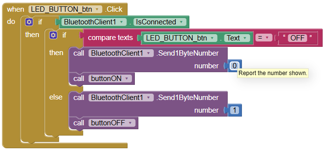
There are two functions in my app one is a button that sends 0 and 1 but the systems shows that it can not decode 0 or 1 as an integer . Second is slider that sends data works fine but on continuous use it hangs Bluetooth module . If I will send text then what will be my range.
As far now my data sending issue has been resolved but i stuck here
when i put variable name "rec" in map() function, and define rec = serial.read(), I receive 0 and 1 perfectly but my slider output goes significantly distorted. When I put serial.read() in this map function, and define as char rec; , my slider output improves 98% but on sending 0 and 1 , I receives only 0s on arduino side. Any idea.
void loop() {
   //Read the value of the pot and map it from 10 to 10.000 us. AC frequency is 50Hz, so period is 20ms. We want to control the power
   //of each half period, so the maximum is 10ms or 10.000us. In my case I've maped it up to 7.200us since 10.000 was too much
   if(Serial.available())
   {
      char rec;
      myvalue = map (Serial.read(),0,255,6700,10);
      Serial.print ("  rec ");
      Serial.println (rec, DEC);
Hi all, this issue was due to receiving my button data as signed character . I changed my receiving code to receive data as unsigned character and that solved this issue . Now there is no more such issue .
There was no serious problem found on the APP side.
Thankyou all and I specially thank to @ABG and @Patryk_F for continuous keeping up with this solution.
Hi, this is the last thing i would like to ask under this topic . Could you please help me with this, How can I send "\n" after each value that slider sends. If not after each value but at least after 2 or 3 values.