Hi,
I am sending round numbers 255 i.e. without decimal to microcontroller. Arduino reads these numbers and controls the voltage that is impressed on some load. when I slide to maximum value, I get reading on Meter as 150 volts . when I slide to minimum value i.e 0 or 1 , Full voltage is available at the output which is unexpected. i want max volt be available at max slider value.
We need to see both sides of the code, transmitting and receiving.
int mydelay = 0;
int myvalue=0;
int last_CH1_state = 0;

void setup() {
  /*
   * Port registers allow for lower-level and faster manipulation of the i/o pins of the microcontroller on an Arduino board.
   * The chips used on the Arduino board (the ATmega8 and ATmega168) have three ports:
     -B (digital pin 8 to 13)
     -C (analog input pins)
     -D (digital pins 0 to 7)
  //All Arduino (Atmega) digital pins are inputs when you begin...
  */

  PCICR |= (1 << PCIE0);    //enable PCMSK0 scan
  PCMSK0 |= (1 << PCINT0);  //Set pin D8 trigger an interrupt on state change. Input from optocoupler
  pinMode(3,OUTPUT);        //Define D3 as output for the DIAC pulse
  Serial.begin(9600);       //Start serial com with the BT module (RX and TX pins)
}

void loop()
{
   //Read the value of the pot and map it from 10 to 10.000 us. AC frequency is 50Hz, so period is 20ms. We want to control the power
   //of each half period, so the maximum is 10ms or 10.000us. In my case I've maped it up to 7.200us since 10.000 was too much
   if(Serial.available()>0)
   {
      myvalue = map(Serial.read(),0,255,7200,10);
      //In my case I've used myvalue = map(Serial.read(),0,255,7000,10); for better results
   }
    if (mydelay)
    {
      delayMicroseconds(myvalue); //This delay controls the power
      digitalWrite(3,HIGH);
      delayMicroseconds(100);
      digitalWrite(3,LOW);
      mydelay=0;
    }
}


//This is the interruption routine
//----------------------------------------------

ISR(PCINT0_vect)
{
  /////////////////////////////////////               //Input from optocoupler
  if(PINB & B00000001){                               //We make an AND with the pin state register, We verify if pin 8 is HIGH???
    if(last_CH1_state == 0){                          //If the last state was 0, then we have a state change...
      mydelay=1;                                    //We haev detected a state change!
    }
  }
  else if(last_CH1_state == 1){                       //If pin 8 is LOW and the last state was HIGH then we have a state change
    mydelay=1;                                      //We haev detected a state change!
    last_CH1_state = 0;                               //Store the current state into the last state for the next loop
    }
}
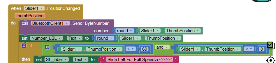
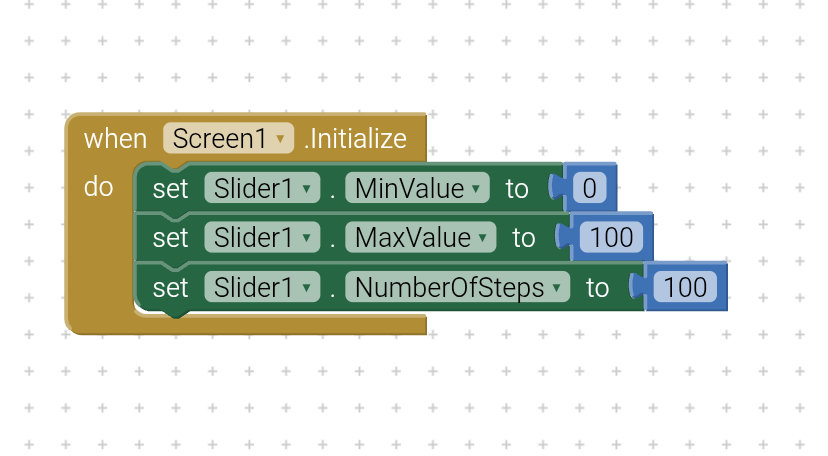
Your AI2 blocks don't show the range of the slider..
We can't check the math without those.
Also, be aware that slider events shoot like fire hoses, very frequently.
Can the data transfer keep up with the slider, or do you need to use a clock timer to slow down the data transfer?
1 Like
I have set the range on the designer view and how to slow down data , what is the required rate.
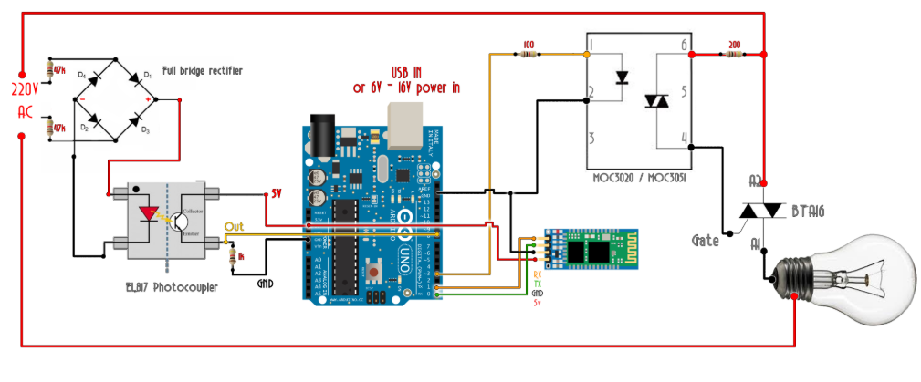
We need one of our hardware guys for this one.
You seem to be controlling the frequency of fixed width square pulses with constant heights to set a DC voltage?
Posting a link to the docs on that map command and its parameters would help, along with hardware information for what you have on pin 3.
Regarding the clock timer driving the transmission, a responsive but frugal approach would be a repeating 30 Ms timer that compares the thumb against a global variable holding the previous cycle thumb value. If the thumb has changed, send the new thumb and save it for the next cycle.
That quiets and slows the data traffic.
The project is simple and working fine except that when I want full voltage to be appeared corresponding to maximum thumb position it achieves that at minimum thumb position.
Second thing is that when I use another button which sends a text "ON" or "OFF" to microcontroller, it interferes with the slider function and changes output but it should not. There could be some issue with my microcontroller code but I wanted to check my AI2 code also . I am keeping UP with hardware Forum also.
Mixing text with byte values in the same data stream is problematic.
I advise just sending text with \n delimiters and have the sketch test for 'on' or 'off' first, else attempt numeric conversion on the input.
There is a read until sketch command for this.
Search this board for the kio4 samples.
If you expect to send more than one data value, like voltage and current, label them with yaml and parse the messages at the receiver.
1 Like
I checked the tool tip for this block
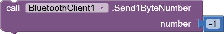
and it does not mention if the 1Byte number it send is signed (-128 to 127) or unsigned (0 to 255).
I don't have a BlueTooth test setup.
It would be interesting to see what byte value arrives.
This is relevant because you use this block and are having trouble with high values.
1 Like
I was looking it up with hardware form and I got 90% problem fixed. As there was issue with optocoupler IC generating large width pulses that created shift in triggering of TRIAC. Now first I will make sure that there is no more problem on hardware side. Yes I need to take care whether my microcontroller understands whether the numbers sent are signed or unsigned, and for that I need to define variables that could store and process those numbers. But i do not know what type of numbers this slider is sending between 0 and 255. Thankyou for your reply.
A properly configured slider will output integers from 0 to 255 in increments of 1.
The problem is in the reverse value mapping:
map(Serial.read(),0,255,7200,10)
It should be:
map(Serial.read(),0,255,10,7200)
1 Like
hi,
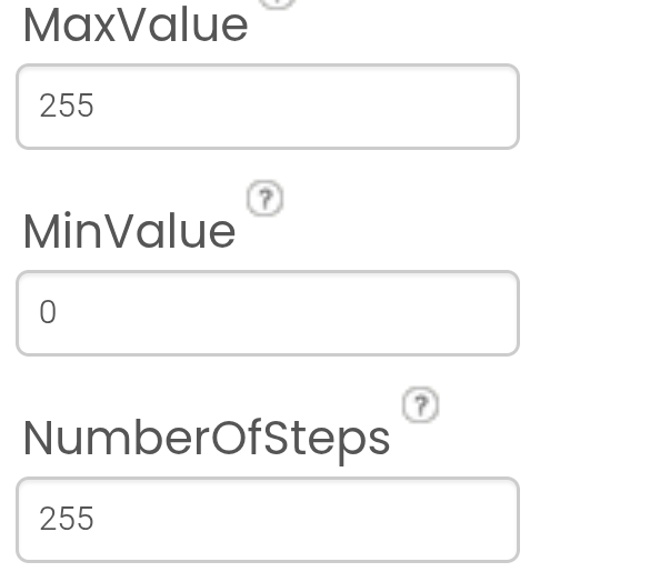
Could you please please tell me how can I set the slider range to send numbers only from 1 - 100 through Bluetooth . All other numbers from 101 - 255 must be dead blocked.
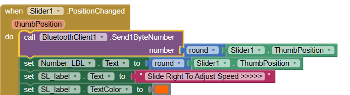
The slider values create interference in the microcontroller as It sends 1 byte number , it takes over the function of other buttons in the app. for example I want to control an Led with a button click to make it on or off . But as I move the slider it makes that LED on or OFF which is unexpected. So i want to block some slider values to reserve them for my LED button.
See the image I shared above? Where the values are 255, enter 100.
I did that I am stuck in a different issue I can not convey here till i will come to some conclusion. Could you please guide me , is there any other way to assign range to to the slider in the blocks view like this
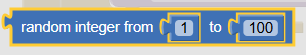
here i can not use this as this will send random integers .
How can I set transmission rate of slider, it seems that microcontroller and bluetooth has low receiving speed than transmitting speed of slider. when my bluetooth module receives data from slider, it gets stuck and app also gets stuck and slider thumb freezes and not moves at all.
Show your blocks that are responsible for sending data from the slider?
What if you modified the Arduino code a bit?
if (Serial.available() > 0) {
  int latestValue;
  while (Serial.available() > 0) {
    latestValue = Serial.read();
  }
  myvalue = map(latestValue, 0, 255, 7200, 10);
}
This will only consider the last value in the buffer and will not leave unnecessary data in the buffer.
1 Like
This is my actual code please suggest edit in this one:
volatile bool mydelay   = false;
int myvalue             = 0;
uint8_t last_CH1_state  = 0;

const int PinDiac       = 3;
const int PinLed        = 11;

enum { LedOn = HIGH, LedOff = LOW };

// -----------------------------------------------------------------------------
void setup () {
  Serial.begin (9600);

  PCICR  |= (1 << PCIE0);    //enable PCMSK0 scan
  PCMSK0 |= (1 << PCINT0);  //Set pin D8 trigger an interrupt on state change. Input from optocoupler

  pinMode       (PinDiac, OUTPUT); //Define D3 as output for the DIAC pulse
  pinMode       (PinLed,  OUTPUT);
  digitalWrite  (PinDiac, HIGH);
  digitalWrite  (PinLed,  LedOff);
}

// -----------------------------------------------------------------------------
void loop () {
  if (Serial.available()) {
        char rec = Serial.read ();

        Serial.print ("  rec ");
        Serial.println (rec, DEC);
    switch (rec)  {
      case '\n':
        break;

      case 0:  // OR ANY VALUE SENT BY THE APP!!!
        digitalWrite (PinLed, LedOff);
        break;

      case 1:  // OR ANY VALUE SENT BY THE APP!!!
        digitalWrite (PinLed, LedOn);
        break;

      default:
        myvalue = map (rec, 0, 180, 6700, 10);  // OR ANY VALUE SENT BY THE APP!!!
        Serial.print   ("  myvalue ");
        Serial.println (myvalue);

        break;
    }
  }

  if (mydelay) {
    delayMicroseconds (myvalue); //This delay controls the power
    digitalWrite      (PinDiac, HIGH);
    delayMicroseconds (100);
    digitalWrite      (PinDiac, LOW);
    mydelay = false;
  }
}

// -----------------------------------------------------------------------------
ISR (PCINT0_vect) {
  uint8_t currentState = PINB & B00000001;
  if (currentState != last_CH1_state) {
    last_CH1_state = currentState;
    // if (currentState == B00000001) { // REMOVE THE IF TO TRIGGER THE PULSE ON BOTH EDGES
    mydelay = true;
    // }
  }
}