Good day, I would like to know how to use the phone's camera to take a picture that loads into the app, and be able to draw straight line segments, and measure angles between them.
Any help will be appreciated
Thanks,
Jakes
Good day, I would like to know how to use the phone's camera to take a picture that loads into the app, and be able to draw straight line segments, and measure angles between them.
Any help will be appreciated
Thanks,
Jakes
Camera
Use the camera component to take a picture, then set the canvas background of the picture you have taken using the afterPicture event
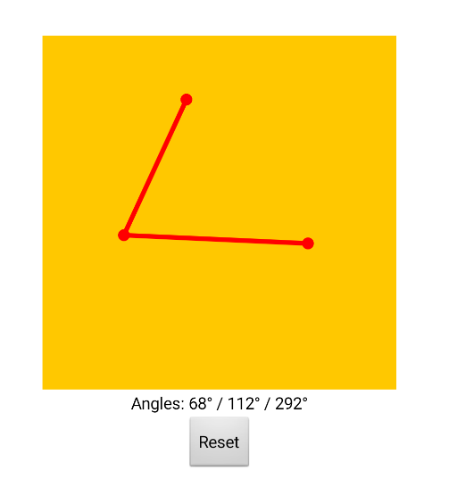
Angles:
Use the drawLine blocks in the canvas to draw lines
This might help you as a starting point:
https://groups.google.com/g/mitappinventortest/c/gsHqd-cNyNM/m/TVYX1K_6BwAJ
You will need to record the relative positions (x1,y1 / x2/y2) of each line, and from there it should be possible to use tan to work out your angle
Attached a simple example of how you might do this ( I am sure the mathematicians will be along to improve.....)
lineAngle.aia (6.9 KB)
Awesome, thanks for the help, will check it out 
Appreciate
Thanks, this is basically what I was looking for.I have changed the app orientation to Landscape, and I have added the camera to capture background image, but the image doesnt keep its perspective (is stretched when applied as canvas background. Cannot get a setting to keep aspect ratio?
Secondly is there a way to edit(Move) the sprites once its placed if misaligned?
Thanks 
You will have to set the canvas to the aspect ratio of the image to avoid stretching/squeezing, there are extensions available to get the height/width of an image which you can use. Alternatively you could use an ImageSprite suitably placed and sized to load the image.
Sprites ? If you mean the circles (dots) and lines, then with this method, no to moving them or realigning. Once drawn, that is it, just reset and set again (it is admittedly easier with a mouse on the emulator than with a fat finger on a screen. With (a lot) more code you could use buttons to nudge a dot to the correct place, before confirming its position. Someone else may have a better approach....)
Or use the touch down / up events to position finger before setting the dot....
Thanks, and if for example have a preset of red dots and lines already placed (for example in the shape of a bicycle frame) the goal is to move the sprites to match the bicycle frame and indicate the angles? Can I for example use Balls, with lines connected?
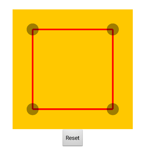
Try this
drawLines.aia (3.9 KB)
The four balls are set to Origin at Centre
You can use the ball x and y positions for the calculations
Watch out for ball/sprite cannibalisn!
Check out the pool cue code in this sample, for how to dynamically move and rotate a line with one end pinned to the Canvas ...
This aia fixes the cannibalism
drawLines2.aia (4.8 KB)
Awesome thanks, I've made good progress. Really appreciate the help.
Is there a way to zoom in on the canvas to make more precise adjustments to the ball positions?
A post was split to a new topic: I cannot get the Canvas to adjust to the aspect ratio of the Image Picker
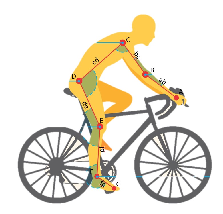
Ok, I have got the canvas and balls to work, and set up a default layout.
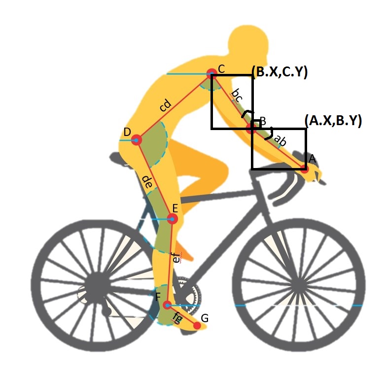
Here is a diagram of lines and angles I require: Angles B-F
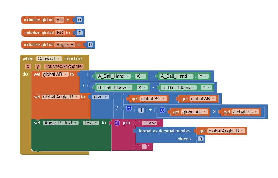
Here are the blocks I have, but doesnt work yet. Any ideas why?
Thanks,
Jakes
I haven't thought through the trigonometry on this, but at first glance it is necessary for your code to take into account the (x,y) values of three Balls:
That's 6 numbers.
I don't see you doing that.
Correct @ ABG
Where is your "slope" calculation for BC ? (refer back to my first example)
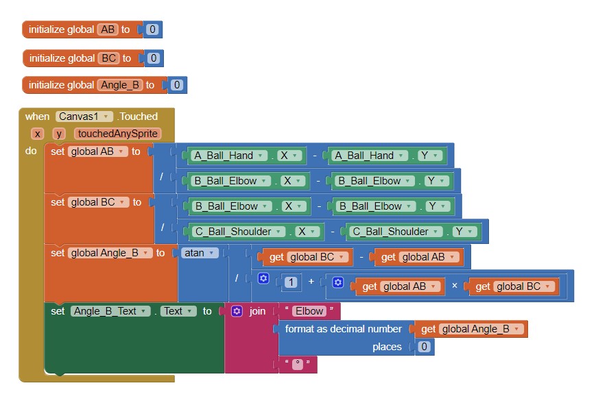
Thanks for the feedback - I missed that. I have added the calculation for BC now, still no luck.
I see in your example you have used a list to get theX,Y points. In my example I tried to get them directly from the balls. Maybe its the issue here?
Assuming the cyclist doesn't scratch his nose or break his elbow,
the angle of his elbow B is going to be obtuse, the sum of 2 acute angles + 90 degrees.
This construction shows the two acute angles:
Heading clockwise around point B, here are the angles to add:
based on the formula tan(acute angle) = opposite side length/adjacent side length
Please note that AI2 uses degrees, not radians.
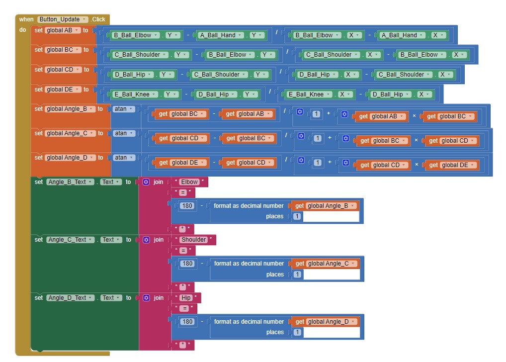
Ok, Ive used formulas to calculate the angle of each segment, and then another formula to calculate the angle between the lines. Working fine, but the moment the angle go over 90 degrees, it shows wrong, For example it works fine from 180 degrees down to 90, but the moment I go less than 90, for example 60 deg, it shows 240.
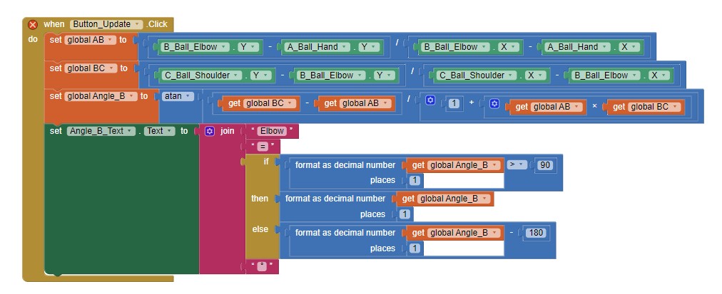
I have tried something similar to this, as well:
Any idea what I can change?
Again, back in my first example, it output all three angles. Somehow, one has to figure out which angle is the correct one to apply, given it all depends on which way around you draw the lines, perhaps a user choice ?