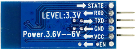
The operation <= cannot accept the arguments: , [*empty-string*], [35]

Hello,

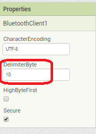
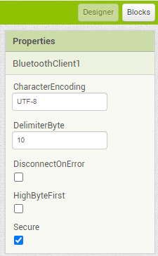
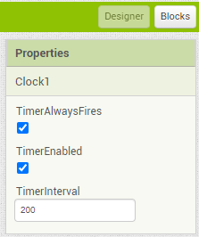
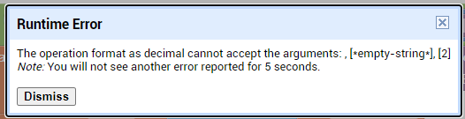
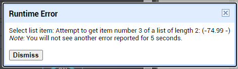
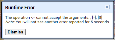
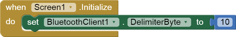
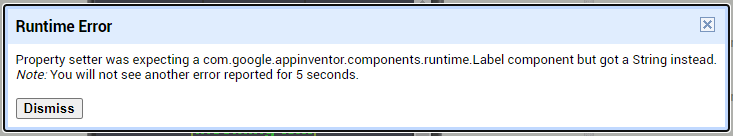
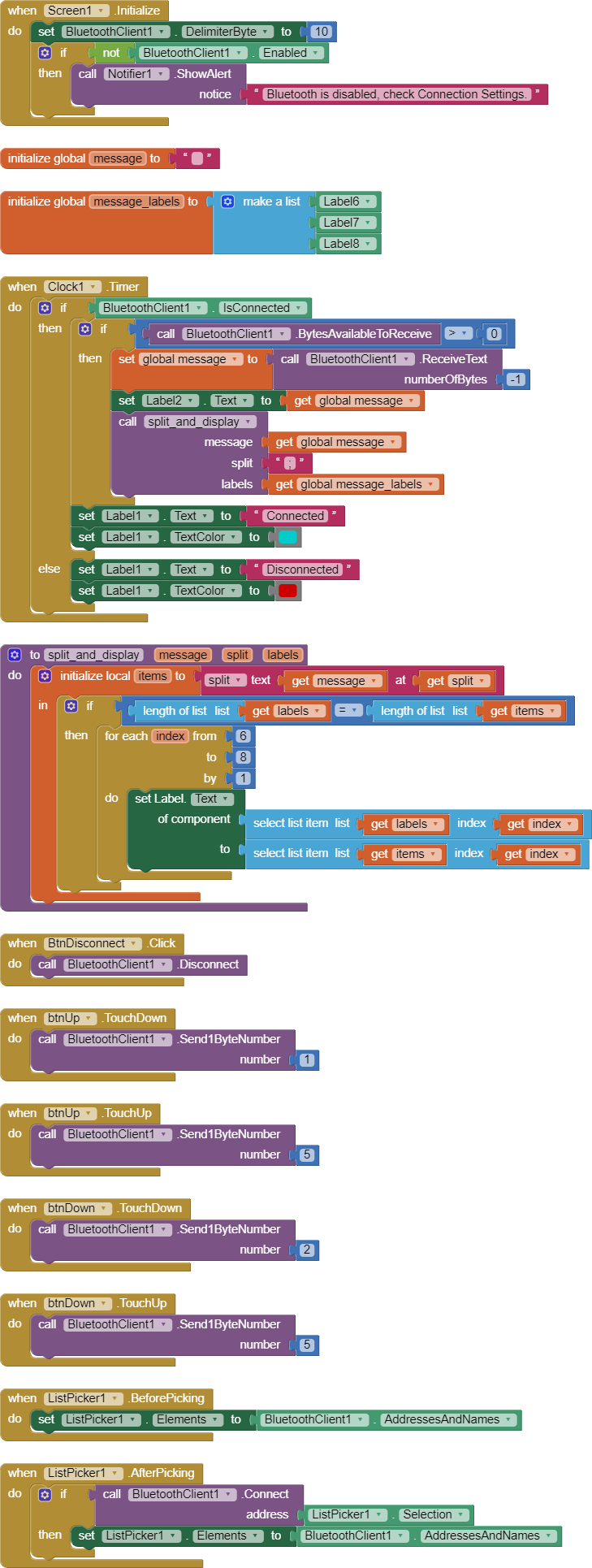
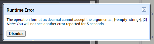
I am trying to make an Android app using MIT App Inventor to read sensor data from and control the onboard LED on an Arduino UNO via a connected Bluetooth module HC-06. I have the Arduino code working as it's sending the correct readings via its Serial Monitor but the same data displayed on the app is a mess. The data values displayed on the app keep fluctuating wildly anywhere between a negative to zero to positive value. I also got the error: The operation <= cannot accept the arguments: , [empty-string], [35] as a popup inside the MIT App Inventor Designer window. I also get a similar error inside the app while testing. The sensor data is of type float up to 2 decimal places. 3 of those float numbers are sent to be displayed in the app but the data seems wrong as all numbers just fluctuate randomly! Those 3 values are sent as a string separated by a semicolon from the Arduino UNO. I have set the app clock timer to 250. The timer loop for sending the data is every 400 loops in the Arduino code. Additionally, i get the following error in the app designer window:
mitapperror
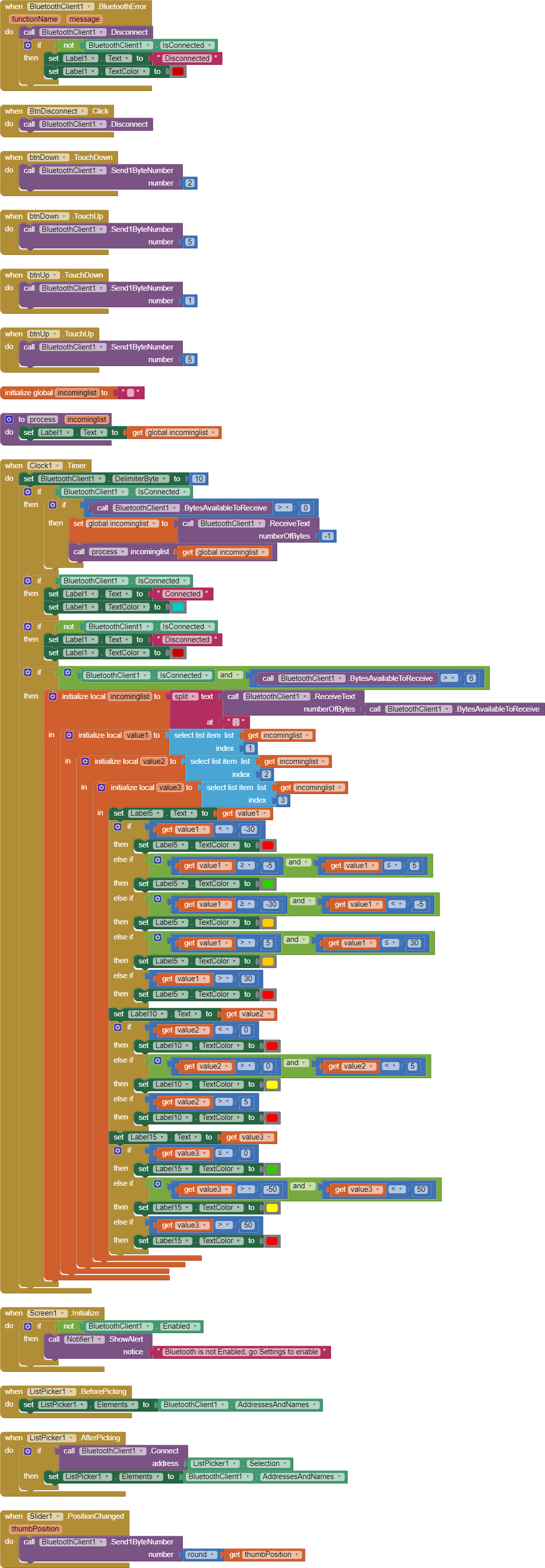
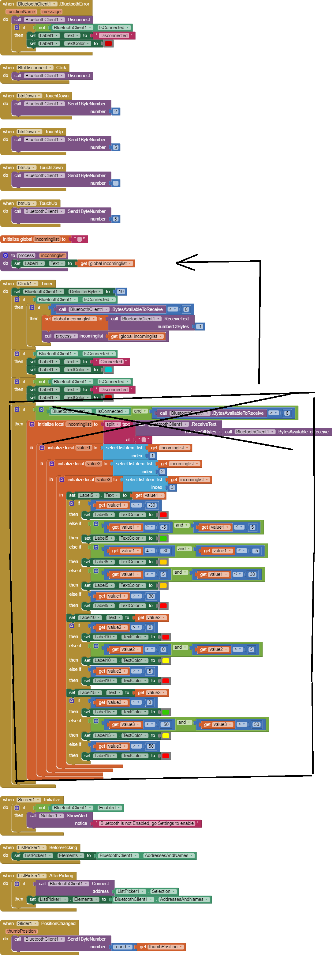
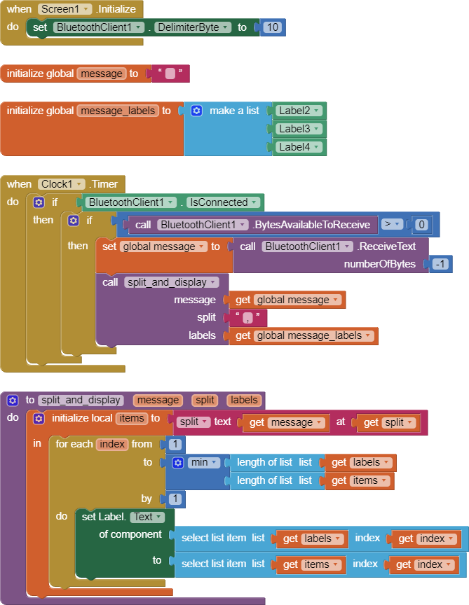
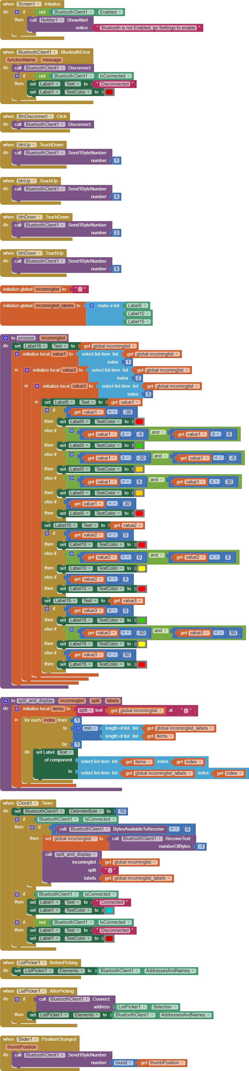
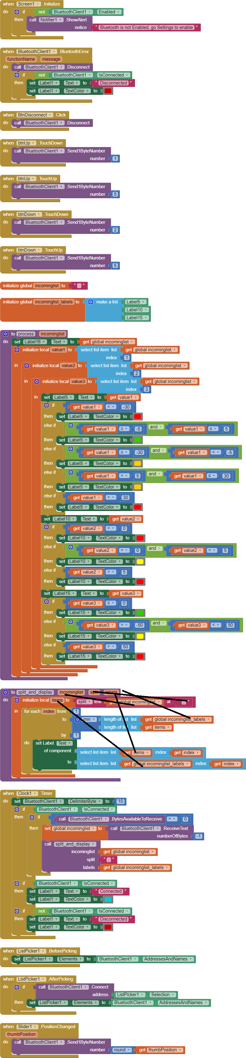
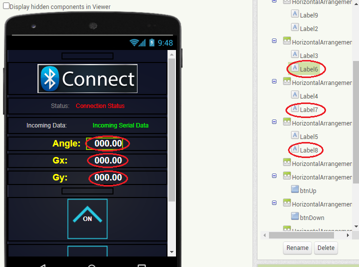
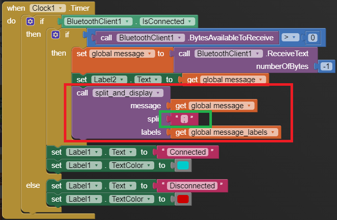
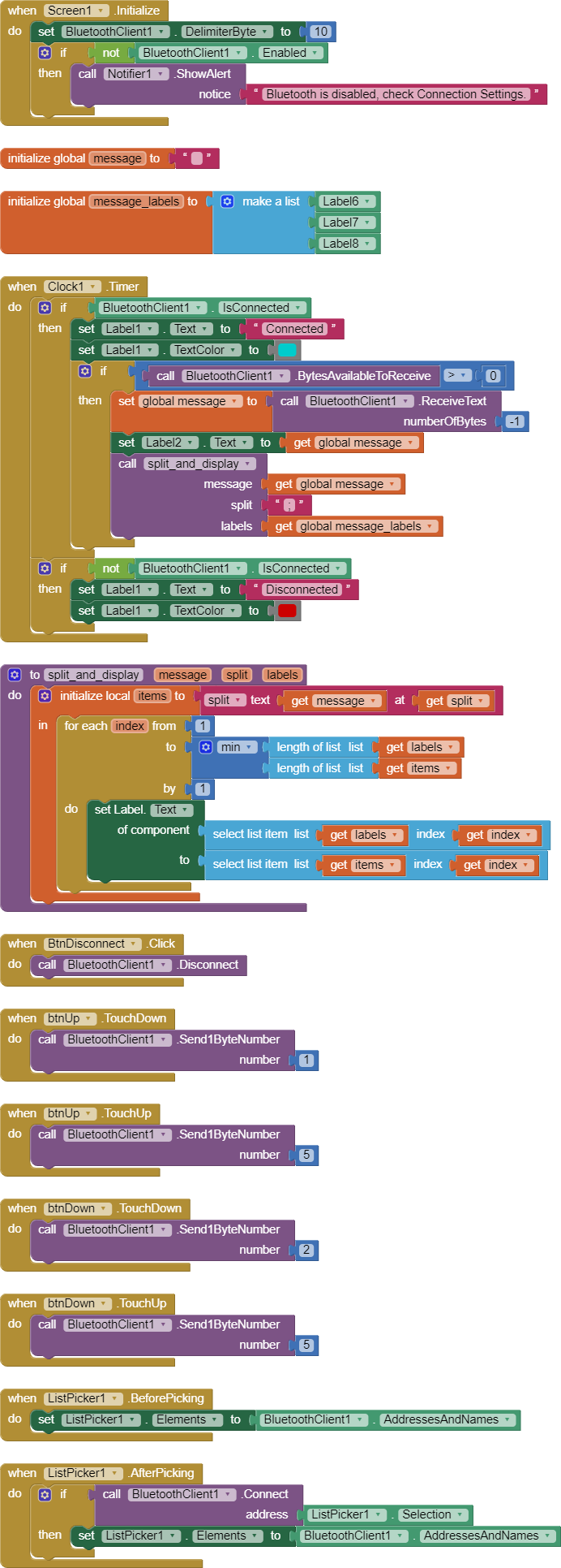
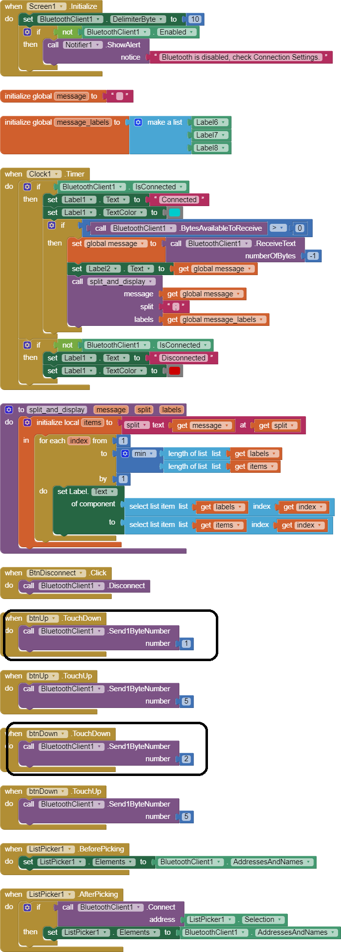
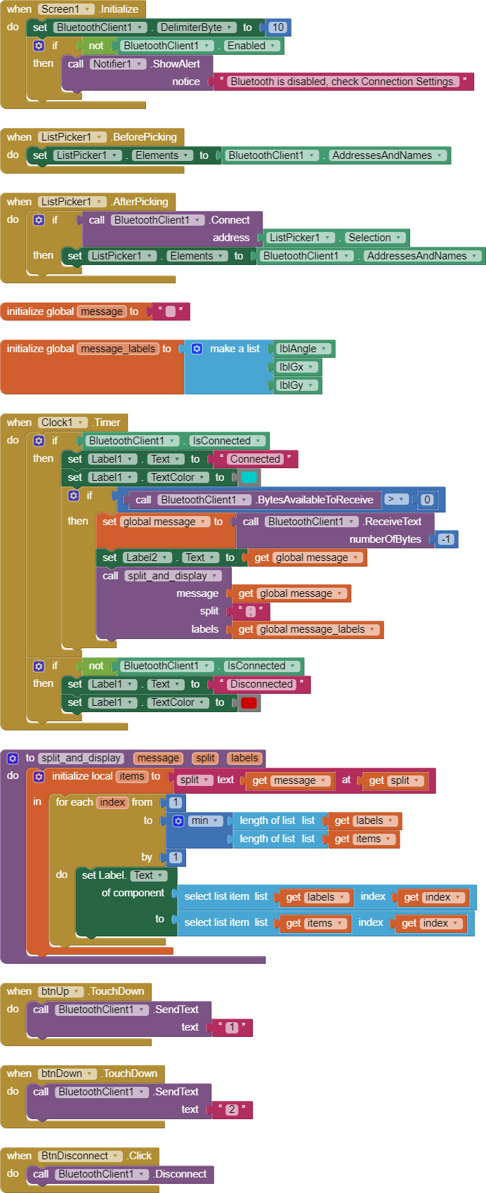
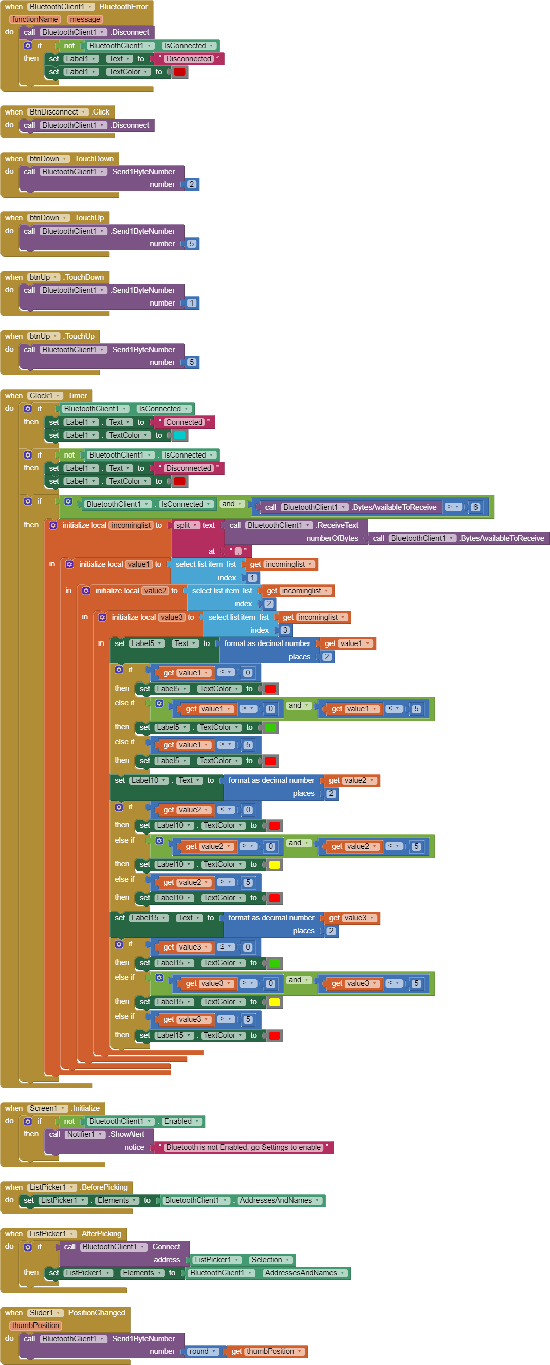
I would really appreciate any help. I have researched on this problem but i have not been able to find exactly how to solve it. Also, are there any suggestions to optimize or improve the stability and performance of my app? I have attached a screenshot of my app blocks. Thanks in advance.


Edit: And here is my Arduino code:
// Arduino UNO code for MIT app to display MPU6050 sensor readings and sending commands

#include <FlexiTimer2.h>    //library to use timer 2 with a configurable resolution.
#include <Wire.h>           //I2C communication library
#include <MPU6050.h>        //MPU-6050 library

MPU6050 accelgyro; 

volatile int16_t ax, ay, az, gx, gy, gz;     //Define three-axis acceleration and three-axis gyroscope variables

int loopCount = 0;

float Gyro_x, Gyro_y, Gyro_z;  //Gyro angular velocity 
float accelAngle = 0;  //calculated tilt angle from accelerometer

char val;

void setup() 
{
  // initialize digital pin LED_BUILTIN as an output.
  pinMode(LED_BUILTIN, OUTPUT);
  
  //join I2C bus
  Wire.begin();                            //join I2C bus sequence
  Serial.begin(9600);                      //open the serial monitor, set the baud rate to 9600
  //delay(1000);
  accelgyro.initialize();                    //initialize MPU6050

  accelgyro.setXAccelOffset(-1784);         //set offset values for the accelerometer and gyroscope.
  accelgyro.setYAccelOffset(88);
  accelgyro.setZAccelOffset(951);
  accelgyro.setXGyroOffset(106);
  accelgyro.setYGyroOffset(-32);
  accelgyro.setZGyroOffset(-6);
  
  delay(4000);  //give enough time for MPU-6050 values to stabilise.
  
  FlexiTimer2::set(5, timerISR);    //run timerISR function every 5ms
  FlexiTimer2::start();             //start timer interrupt
}

void loop()
{
  
  if(Serial.available())
  {
    val = Serial.read();      //assign the value read from serial port to variable val
    
    switch(val)  //switch case statement
    {
      case '1': 
        digitalWrite(LED_BUILTIN, HIGH);   // turn the LED on (HIGH is the voltage level)
        Serial.println("LED ON");
        break;       
      case '2': 
        digitalWrite(LED_BUILTIN, LOW);   // turn the LED on (HIGH is the voltage level)
        Serial.println("LED OFF");
        break;
    
    }
    
    if(val > '2')
    {
      Serial.println("Value received > 2");
    }

  }

    // loop counter
    loopCount = loopCount + 1;
    
    // when counter value exceeds 400 loops, 
    // the sensor data is sent to the app every 401 loops.
    // and counter value reset to zero. 
    if(loopCount > 400)
    {
     //By default, Serial. print() prints floats with two decimal digits.
     Serial.print(accelAngle);        //send tilt angle to App
     Serial.print(";"); //delimiter for variables so the app can distinguish between them
     Serial.print(Gyro_x); 
     Serial.print(";");
     Serial.print(Gyro_y);
     Serial.println(";");
     loopCount = 0; //reset loop count timer
    }
}


void timerISR()
{
  interrupts();   //Re-enable interrupts
  accelgyro.getMotion6(&ax, &ay, &az, &gx, &gy, &gz);     //IIC to get MPU6050 six-axis data ax ay az gx gy gz
  angle_calculation(ax, ay, az, gx, gy, gz);      // get angle
}

void angle_calculation(int16_t ax, int16_t ay, int16_t az, int16_t gx, int16_t gy, int16_t gz)
{
  accelAngle = -atan2(ay, az) * (180/ PI); //tilt angle from accelerometer
  Gyro_x = -gx / 131.0; //angular speed of X-axis from gyro
  Gyro_y = -gy / 131.0; //angular speed of Y-axis from gyro
}

And here is a sample output from the Arduino Serial Monitor, which shows the data being sent via the Bluetooth module to the MIT app:

32.43;-35.56;4.03;
37.92;-130.60;5.89;
34.74;-207.77;4.78;
28.08;-250.13;0.15;
17.53;-250.13;-1.05;
36.15;-250.13;0.55;
-9.25;-250.13;-1.69;
-28.78;-250.13;-1.00;
-24.00;-250.13;-1.21;
-38.41;-250.10;-1.30;
-45.01;-114.19;-2.30;
-45.17;-27.47;-0.15;
-39.24;6.06;-0.57;
-41.50;36.79;-0.12;
-48.84;184.22;-0.50;

It would help if we saw your Arduino code too.

In the meantime, here is the probable fix ...

Please see the Delimiter article in FAQ

Be sure to use println() at the end of each message to send from the sending device, to signal end of message. Do not rely on timing for this, which is unreliable.

In the AI2 Designer, set the Delimiter attribute of the BlueTooth Client component to 10 to recognize the End of Line character.
BlueToothClient1_Properties
Also, return data is not immediately available after sending a request,
you have to start a Clock Timer repeating and watch for its arrival in the Clock Timer event. The repeat rate of the Clock Timer should be faster than the transmission rate in the sending device, to not flood the AI2 buffers.

In your Clock Timer, you should check

  Is the BlueTooth Client still Connected?
  Is Bytes Available > 0?
     IF Bytes Available > 0 THEN
       set message var  to BT.ReceiveText(-1) 

This takes advantage of a special case in the ReceiveText block:

ReceiveText(numberOfBytes)
Receive text from the connected Bluetooth device. If numberOfBytes is less than 0, read until a delimiter byte value is received.

If you are sending multiple data values per message separated by | or comma, have your message split into a local or global variable for inspection before trying to select list items from it. Test if (length of list(split list result) >= expected list length) before doing any select list item operations, to avoid taking a long walk on a short pier. This bulletproofing is necessary in case your sending device sneaks in some commentary messages with the data values.

1 Like

First, thanks for your precious advice. It's much appreciated. I have edited the first post to add my full Arduino code alongside a sample output from the Arduino Serial Monitor. I tried to make the changes based on your suggestions:

I have implemented this part in the Arduino code. I hope it's correct.

Serial.print(accelAngle); //send tilt angle to App
Serial.print(";"); //delimiter for variables so the app can distinguish between them
Serial.print(Gyro_x);
Serial.print(";");
Serial.print(Gyro_y);
Serial.println(";");

Here are my settings. I hope these are correct.
BTclientapp

clockapp
I think i should probably use millis() in my Arduino code to time it more accurately, since i only used the number of loops as a way to time the data sent to app via the Bluetooth module. I have set the sensor data to be sent every 400 loops from the Arduino, but i am not sure if it takes more than 200ms to cycle through the loop 400 times. For now, i just increased the number of loops in the Arduino code to 800. This should be more than 200 ms. But i get this error, both in the App Designer window and the Android app.
mitappruntime

Here is what i managed. I'm not sure if it's the best approach though.


And i get this new error:
mitappruntime2
And one more error:
mitruntime3
I'm not sure what's wrong and how to fix these errors.

You failed to remove the old code that was asking for incomplete messages.
(See above.)

The processing of the message that was received properly should have been put inside the procedure that was fed the properly received complete message.
This is a good time to review the chapter on procedures in the free book at
http://www.appinventor.org/book2

You also failed to grab the split message into a variable and check the length of list BEFORE trying to select list items from it.

Here is an updated blocks sample illustrating these ideas ...

BlueTooth_delimiter_sample.aia (3.4 KB) global message

1 Like

I removed the old portion of code and i tried to rework it from the updated blocks sample. But i'm getting this error and the app doesn't work at all.

In one of the sample blocks from your reply above, the Screen1.Initialize has the DelimiterByte block but in my blocks, the DelimiterByte block is under the Clock1.Timer block. What's the difference? Is one more efficient than the other?

Here are the updated blocks. I made a few changes to make the app easier to understand or troubleshoot. I added a new label16 to show the full incoming message from the Arduino. Also, from the app designer, the labels which show the 3 sensor data are: label 5, 10 and 15. So, i'm not sure if incrementing it by 1 will work, like in the split_and_display block? But maybe i'm not understanding the splitting procedure correctly.

I added parameters to the procedure for a reason, to help generalize it for different people, and to name the inputs to avoid confusing them with each other.

That did not stop you, however.

Go back and read that chapter on procedures, especially the part on parameters.

And when some one gives you a self contained procedure with input parameters, don't smash it open, scramble it, and expect it to work.
(Likewise for your household electronics. Respect the voiding warrantee label.)

P.S. my procedure blocks were draggable directly into the Blocks Editor from the thread.

I apologize for rushing into it with the sample blocks that you provided. I'll go through the chapter again as you suggested and give it a closer look. I'll come back when i have a better understanding. Thank you for your help and patience.

I am sorry for my delayed response. I finally read the whole chapter on Procedures as suggested. It took me some time to grasp the concept of procedures in AI2 being similar to functions as well as formal vs actual parameters but i believe that i have a better understanding now. So, i reworked the AI2 blocks and also removed the extra blocks which were not essential at this point.

While testing in the app, the labels 6, 7 and 8 are not displaying anything. They should show the 3 items or split parts of the message. Also, label 2 should display the full incoming serial data or message but it is not correct. The actual serial data fluctuates between positive and negative but on the app, it doesn't show the updated correct data. I turned off the Arduino and oddly, the app still kept displaying incoming serial data from the Arduino Bluetooth in label 2.

I also made an attempt based on the following suggestion but i'm not sure if my approach is correct? I basically compared the number of labels to the number of items to check for errors in the incoming data. From my understanding, if both are 3, then it should be a non-corrupted incoming serial data message that can be displayed in the app?

I also got this Runtime Error in App Inventor Blocks window:

Select list item: Attempt to get item number 6 of a list of length 3: (com.google.appinventor.components.runtime.Label@6688c39 com.google.appinventor.components.runtime.Label@dbe282c com.google.appinventor.components.runtime.Label@172defb)
Note: You will not see another error reported for 5 seconds.

You have a mismatch between your expectations for list indices of your semicolon separated messages and the length of the list of labels this procedure would assign values to.

You broke the original procedure.

Where did you get the 6,7,8 from?

P.S. I reread your post, and now suspect you are thinking of list indices as names, and not of their positions (1,2,3,....) of items in a list.

The original procedure I gave you would have worked just fine (assuming you actually used ';' between items in your messages, which you did not show recently.)


From my understanding, if the number of labels which is a fixed global variable (value = 3) is equal to the number of split parts (this should have a value of 3 if there are no anomalies in the data received). Then, the program proceeds to assign label 6 to the first split part of the data, label 7 to the second split part and label 8 should contain the third split part of the data received. At least, that's what i tried to do. But for some reason, it didn't work.

Below is the original block that you posted:


But the "min" block (from my understanding) is simply comparing the number of labels which is fixed to a value of 3, and the number of the items or split parts from the received data, and whichever is the smallest is returned as the max value or limit to that range. But i think that would not work for this application? Since, the program should be doing a test to check if the number of labels match the split parts or items. I'm confused about why this "min" part is needed.

These are the labels which should display the 3 values split from the incoming message. The labels 6, 7 and 8 are listed in that order and displayed from top to bottom in the app interface.

Yes, i used semicolon to split the data. The sample data from the Arduino Serial Monitor also shows the same, as in the quote at the end of the first post in this thread. As shown below, i put the semicolon in the Clock1. Timer block, under the call split_and_display block. The semicolon block is fed as an actual parameter in the call block.
splitblock

Edit: OK, i gave it more thought and i think maybe i understand the reason for using the "min" block. So, here is a sample of the incoming data or message expected:

32.43;-35.56;4.03;
37.92;-130.60;5.89;
34.74;-207.77;4.78;
28.08;-250.13;0.15;

So, let's say there is a data corruption (i suppose this would be additional text displayed on the Arduino Serial Monitor based on given commands typed in the Serial Monitor or sent from the app) after the third split part, then only the first 3 parts will be considered and displayed. Am i correct in understanding the reason behind the "min" block? What are other types of data corruption that would require the "min" block?
Like this example:

32.43;-35.56;4.03; This is extra text typed in Arduino Serial Monitor or sent from MIT app
37.92;-130.60;5.89;
This is extra text typed in Arduino Serial Monitor or sent from MIT app
34.74;-207.77;4.78;
28.08;-250.13;0.15;

I made the following changes as suggested and the app labels work now but the incoming data is extremely slow to change (it can take up to 30 seconds or more!) compared to how fast it changes in the Arduino Serial Monitor. It seems like it is buffering all the incoming data but it is taking too long to update it in the app labels. How to fix this?
Edit: I solved this by decreasing the TimerInterval to 100 ms and increasing the Loop interval time for data sent from the Arduino to 300 ms. This combination seems to work fine with almost instant data displayed in the app labels. There is a slight lag but i guess this is unavoidable.

The only problem now is that the commands sent from the app is not working. The up and down buttons in the app should turn ON or OFF the onboard LED on the Arduino. When the BT module is unplugged and the Arduino UNO connected to the PC via USB cable, i can control the onboard LED by typing the value 1 or 2 in the Arduino Serial Monitor. But after i connect the BT module to the Arduino UNO, i tried the ON and OFF buttons in the app but neither work. Any suggestions?

AI2 lets you rename components in the Designer, to help
make the blocks easier to understand.

Suggested renames:
Label6 ==> lblAngle
Label7 ==> lblGx
Label8 ==> lblGy

As you guessed, the min() trick avoids any chance of an error message if the number of labels does not match the number of readings in a message,

Regarding the Arduino control problem, post a new copy of your Arduino code and maybe a wiring diagram for the hardware guys.

1 Like

The entire Arduino hardware setup is quite straight-forward. I double-checked all the wirings, including between the Arduino UNO R3 and the HC-06 Bluetooth module.


I also have an MPU6050 sensor connected to the UNO. When the Bluetooth module is disconnected, the hardware is working as expected via the Arduino Serial Monitor, that is, there are no issues when outputting sensor data and sending commands via the Arduino Serial Monitor. The problem is the following:

The commands sent from the app are not working (although sensor data from the Arduino is being displayed correctly in the app and updated at a fixed time interval). The up and down buttons in the app should turn ON and OFF the onboard LED on the Arduino. When the BT module is unplugged and the Arduino UNO is connected to the PC via USB cable, sensor data is shown in the Arduino Serial Monitor and i can also control the onboard LED by typing the value 1 or 2 in the Arduino Serial Monitor. But after i connect the BT module to the Arduino UNO, i tried the ON and OFF buttons in the app but neither work.

Here is my updated Arduino code. The main change that i made from the initial version in the first post, is the use of millis to time the sensor data output more precisely instead of relying on the number of loops. This was necessary to time it relative to the app Clock TimerInterval set to 100.

#include <FlexiTimer2.h>  
#include <Wire.h>        
#include <MPU6050.h>   

MPU6050 accelgyro; 

volatile int16_t ax, ay, az, gx, gy, gz;     //Define three-axis acceleration and three-axis gyroscope variables

float Gyro_x, Gyro_y, Gyro_z;  //Gyro angular velocity 
float accelAngle = 0;  //calculated tilt angle from accelerometer

char val;

unsigned long startMillis; 
unsigned long currentMillis;
const unsigned long period = 300;  

void setup() 
{
  // initialize digital pin LED_BUILTIN as an output.
  pinMode(LED_BUILTIN, OUTPUT);
  
  //join I2C bus
  Wire.begin();                            //join I2C bus sequence
  Serial.begin(9600);                      //open the serial monitor, set the baud rate to 9600

  accelgyro.initialize();                    //initialize MPU6050

  accelgyro.setXAccelOffset(-1784);         //set offset values for the accelerometer and gyroscope.
  accelgyro.setYAccelOffset(88);
  accelgyro.setZAccelOffset(951);
  accelgyro.setXGyroOffset(106);
  accelgyro.setYGyroOffset(-32);
  accelgyro.setZGyroOffset(-6);
  
  delay(4000);  //give enough time for MPU-6050 values to stabilise.
  
  FlexiTimer2::set(5, timerISR);    //run timerISR function every 5ms
  FlexiTimer2::start();             //start timer interrupt
  
  startMillis = millis();  //initial start time
}

void loop()
{
  currentMillis = millis();  //get the current "time" (actually the number of milliseconds since the program started)
  
  if(Serial.available() > 0)
  {
    val = Serial.read();      //assign the value read from serial port to variable val
    
    switch(val)  //switch case statement
    {
      case '1': 
        digitalWrite(LED_BUILTIN, HIGH);   // turn the LED on 
        Serial.print("******************** ");
        Serial.print("LED ON");
        Serial.println(" ********************");
        break;       
      case '2': 
        digitalWrite(LED_BUILTIN, LOW);   // turn the LED off 
        Serial.print("******************** ");
        Serial.print("LED OFF");
        Serial.println(" ********************");
        break;
    }
  }
    
  // the sensor data is sent to the MIT app every 300 ms.
  if (currentMillis - startMillis >= period)  //test whether the period has elapsed
  {
    //By default, Serial. print() prints floats with two decimal digits.
     Serial.print(accelAngle);        //send tilt angle to App
     Serial.print(";"); //delimiter for variables so the app can distinguish between them
     Serial.print(Gyro_x); 
     Serial.print(";");
     Serial.print(Gyro_y);
     Serial.println(";");
    
    startMillis = currentMillis;  //to save the new start time.
  }
}

void timerISR()
{
  interrupts();   //Re-enables interrupts
  accelgyro.getMotion6(&ax, &ay, &az, &gx, &gy, &gz);     //IIC to get MPU6050 six-axis data ax ay az gx gy gz
  angle_calculation(ax, ay, az, gx, gy, gz);      // get angle
}

void angle_calculation(int16_t ax, int16_t ay, int16_t az, int16_t gx, int16_t gy, int16_t gz)
{
  accelAngle = -atan2(ay, az) * (180/ PI); //tilt angle from accelerometer
  Gyro_x = -gx / 131.0; //angular speed of X-axis from gyro
  Gyro_y = -gy / 131.0; //angular speed of Y-axis from gyro
}

I thought that maybe having the UNO connected via USB cable to my PC is what's causing this communication issue with the BT module and MIT app. So, i tried to power the Arduino via USB separately from a charger but same problem - the MIT app control buttons don't have any effect. Maybe instead of powering the Arduino via its USB port (which i'm guessing might be interfering with the RX and TX transmissions from the BT module), i should power it via its power connector? But i'm not sure if it's going to make any difference. Any advice is very welcome.

Hc06 on tx and rx communication lines, accepts logical states up to 3.3V. Arduino works at 5V. So you may need a logic converter.

The HC-06 module that i use looks like this:
hc-06back
I don't have a logic converter on hand so i am thinking of building a voltage divider using resistors for the RX pin. But is this actually the reason why the data sent from the app is not being processed? I have used the HC-06 successfully in other apps with Arduino where i just needed to send commands from the app. But for this particular app, i think the sensor data streamed to the app at a regular clock timer interval might be messing up the commands sent. The HC-06 has duplex communication so maybe it got messed up somehow in the app?

Yes. Without a logic converter, your app will receive information from arduino, while arduino will not read data from the app.

Yes, you can make a voltage divider.

Your Arduino code expects characters '1' and '2' (decimal 49 and 50)

if(Serial.available() > 0) 
 { val = Serial.read(); //assign the value read from serial port to variable val switch(val) 
//switch case statement   { 
 case '1': 
    digitalWrite(LED_BUILTIN, HIGH); // turn the LED on 
    Serial.print("******************** "); 
    Serial.print("LED ON"); 
    Serial.println(" ********************"); 
    break; 
case '2': 
  digitalWrite(LED_BUILTIN, LOW); 
  // turn the LED off 
  Serial.print("******************** "); 
  Serial.print("LED OFF"); 
  Serial.println(" ********************"); 
  break; 
 } 
}

but your AI2 code sends values of 1 and 2 decimal byte values.


Look in the BlueTooth component blocks for the block that sends text, and use the text blocks for '1' and '2'.

2 Likes

Yes that's true. I focused too much on "not receiving data" instead of "incorrectly receiving" :slight_smile:

It worked! Thanks for finding the mistake in my code.

I still appreciate your help. Thanks for the hint about the logic converter even though it seems to be working without it for some reason. But to be safe, maybe i'll try to connect a voltage divider.

There are a few things which i am trying to iron out and understand:

  1. Whenever i start the app for the first time and i connect to the Arduino HC-06 module from the list of BT devices, i see a Bluetooth connection error in the app:

Error 507. Unable to connect. Is the device turned on?

The Arduino and HC-06 module are already connected properly and powered on. But i have to try to connect in the app at least 2 or 3 times before it finally establishes a connection. Is there a better way to build the Bluetooth blocks so the initial connection is done properly? Otherwise, what could be the reason/s behind these errors?

  1. Is there a way to make the data update faster from the Arduino to the app labels? I could increase the data rate sent from the Arduino from its current 300ms loop to maybe 100ms. But then, from what i understood, the clock TimerInterval has to be faster, but what is its limit without crashing the app or showing corrupt data? Currently, i have set the clock TimerInterval to 100ms.

  2. The Bluetooth Client DelimiterByte block is currently placed under the Screen1.Initialize block. But from what i've seen in some other MIT Inventor apps, the Bluetooth Client DelimiterByte block was placed under the Clock1.Timer block. Which one is better/more efficient or does it not matter at all?

  3. I want to add more button controls to the app and to make it less cluttered, i am thinking of moving some of the controls to a second screen accessible from a menu button on the main app screen. What is the recommended way of doing this?

This is the current status of my app:

That was probably because when I made sample blocks, I was too lazy to add the Screen1.Initialize block, where the initial Delimiter setting belonged more than in the Timer event, which is a bit wasteful of run time. I had to show the Timer event anyway, so I stuck it there. I used to show it in the Designer, but some folks thought it was more instructive in blocks. It is more drag-worthy in blocks than in the Designer.

1 Like