So I don't understand why in the listpicker I see the screen all black even though I'm connected to the HC-05 but it only flashes more slowly and not "double".
Do I have to put some blocks to connect it?
What did I do wrong?
Did you ask for permission?
Taifun
(Canned Response ABG - Bluetooth non-BLE SCAN Permission Blocks)
The easiest solution, for immediate relief
(from @Barry_Meaker) ...
I had the same issue. The problem is your app does not have permission to see nearby devices. The solution is to give your app permission on your phone (no code changes in your app).
on your phone,
- goto settings
- search for your app
- in App Info for your app select Permissions
- change Nearby Devices from Not Allowed to Allowed
- Done
By the way, the very first time you run the app, Android will ask if you want to grant the app this permission. If you say no, or ignore the pop-up, the permission will be set as Denied. Android will not ask again.
A more complex approach, for professional app development:
See Bluetooth liste of devices deosn't work anymore - #7 by Anke
Special note for Xiaomi devices:
I have an error with bluetooth on android 12, Xiaomi Poco X3 NFC - #20 by Patryk_F
Thanks for the reply but I had already set all the permissions. I also tried "I have an error with bluetooth on android 12" but it doesn't work. So the problem is my phone? I have the Samsung Galaxy A21S.
It would really help if you provided a screenshot of your relevant blocks, so we can see what you are trying to do, and where the problem may be.
To get an image of your blocks, right click in the Blocks Editor and select "Download Blocks as Image". You might want to use an image editor to crop etc. if required. Then post it here in the community.
Taifun
Trying to push the limits! Snippets, Tutorials and Extensions from Pura Vida Apps by ![]() Taifun.
Taifun.
you did not use blocks to ask for permissions, see again Bluetooth liste of devices deosn't work anymore - #7 by Anke
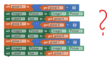
also what is this?
Taifun
1 Like
That piece is the purpose of the project. With Arduino I have to detect three objects of different shapes and send them to the application but to see a single warning I put them together. I haven't put them on yet because I haven't connected Bluetooth yet.
Now it connects to Bluetooth but the characters the Arduino receives are these: � or
.
What should I do?
Post the new code, both sending and receiving.
Dear @minalbero,
probably it's trivial, but which baudrate have you set for the Serial Monitor to the PC ?
The "weird" characters can be caused by a wrong baudrate or if you use Serial.write instead of Serial.print (i.e. numerical representation instead of ASCII). This second case should not be yours if your Arduino code is the same as you posted in your first post.
As @ABG have said, please post your last Arduino code.
PS last but not least, are you sure that the HC05 baudrate is 9600 ? I've had in few cases some of them factory set @38400 
SECOND EDIT: but you say that the HC05 is blinking every two seconds ? If yes, this means that it is set in AT mode !! So it is in programming mode, not in communication mode 
2 Likes
Thx, now i set baudrate 38400 and work.
Thank all you 
Dear @minalbero,
I'm happy that it works. So your HC05 has both comm's and programming speed set @38400.
Is it one of those that remain with a steady red led ON or is it blinking slowly once (or twice) ?
(So to recognize the type and to help someone else, the next time  ).
).
Cheers, Ugo.
The HC-05 blinking slowly twice
Now I have two other problems:
- now that I have the connection there is a conflict between what I transmit via bluetooth and the physical one
- the LCD screen doesn't work.
To better understand this is the delivery:
Design a device that allows you to count objects of different shapes that slide on a conveyor belt, and sort them.
Objects with three different shapes slide on the belt.
The shapes, seen from above and from the side, slide on the surface resting on the base, as in the lower view, but with a random angle of
orientation.
Device operating specifications:
The device must recognize and count objects of each shape, and for each recognized shape a digital signal must be activated
which will allow the object to be sorted by diverting it onto other belt paths intended for packaging, this last phase involves the collection
of objects in packs of 10 pieces, for each type of object.
Objects on the conveyor belt will be sensed using infrared devices.
The quantity of objects counted and the number of packages made, for each type, must be displayed on an LCD display and also
sent, via Bluetooth or WiFi, to a terminal (PC, smartphone, other) for viewing.
The control device must also be equipped with a button that will allow, at any time, to start the conveyor belt or
arrest him. The same button function must also be possible by sending a command from the remote terminal. When the tape stops they will be
object detection sensors are also inhibited. The movement of the tape (active tape) must be indicated by the lighting of a
Green LED. A red LED will indicate the tape stopped status. Conveyor belt motor will be driven (belt moving)
via a low level digital signal, which will assume the high state when the motor is stopped (belt stopped).
Technical specifications:
The objects have homogeneous dimensions: square base with side 9cm and height 3cm; the elevated part of object B is a cube, in position
central, with a side of 3cm, while the elevated part of object C is a parallelepiped measuring 3cm x 9cm x 3cm high placed on one side.
The sorting signals must be of the impulsive type, active at a low level, with a duration of 20ms.
The conveyor belt has a width of 20 cm.
The time between the passage of two consecutive objects in front of the sensors is at least 200 ms, during which they must be
all the actions described above are guaranteed.
This is the Arduino program:
Blockquote#include
<SoftwareSerial.h>
#include "LCD03.h"
const int switchPin = 12; // the switch connects to pin 12
const int redPin = 10;
const int greenPin = 11;
const int pinMotor1 = 8;
const int pinMotor2 = 9;
// Configurazione dei pin per il display LCD
const int rs = A0; // Pin RS collegato ad A0
const int en = 13; // Pin E collegato al pin 13
const int d4 = 2; // Pin D4 collegato al pin 2
const int d5 = 3; // Pin D5 collegato al pin 3
const int d6 = 4; // Pin D6 collegato al pin 4
const int d7 = 5; // Pin D7 collegato al pin 5
LiquidCrystal lcd(I2C_ADDR, en, rs, d4, d5, d6, d7);
//
int switchState = 0; // variable for reading the pushbutton status
char on_off = '0'; // Change to character '0'
SoftwareSerial bluetooth(6, 7); // RX, TX - change these pins as needed
void color(unsigned char red, unsigned char green, unsigned char blue) // the color generating
{
analogWrite(redPin, red);
analogWrite(greenPin, green);
}
void setup()
{
pinMode(switchPin, INPUT); // initialize the buttonPin as input
pinMode(pinMotor1, OUTPUT);
pinMode(pinMotor2, OUTPUT);
Serial.begin(38400);
bluetooth.begin(38400); // initialize SoftwareSerial for Bluetoot
}
//
void loop()
{
// read the state of the switch value
switchState = digitalRead(switchPin);
if (switchState == HIGH)
{
on_off = '1';
}
else if (switchState == LOW)
{
on_off = '0';
}
if (bluetooth.available() > 0)
{
char receivedChar = bluetooth.read();
Serial.print("Received char: ");
Serial.println(receivedChar);
receivedChar = on_off;
if (receivedChar == '1')
{
on_off = '1'; // Change to character '1'
//switchState = HIGH;
Serial.println("Acceso");//turn on
}
else if (receivedChar == '0')
{
on_off = '0'; // Change to character '0'
//switchState = LOW;
Serial.println("Spento");//Turn off
}
}
//switchState = digitalRead(switchPin);
Serial.print("Switch state: ");
Serial.println(switchState);
Serial.print("on_off value: ");
Serial.println(on_off);
if (switchState == HIGH && on_off == '1') // if it is, the state is HIGH
{
color(0, 255, 0); // turn the led on
digitalWrite(pinMotor1, HIGH);
digitalWrite(pinMotor2, HIGH);
lcd.clear();
lcd.print("Oggetto ");
lcd.print(pieceType);
lcd.print(": ");
lcd.print(objectCount[pieceType - 1]);
if (shouldProducePackage()) {
for (int i = 0; i < maxObjects; i++) {
totalPackages[i] += objectCount[i];
objectCount[i] = 0;
}
displayTotalPackages();
}
else if (switchState == LOW || on_off == '0')
{
color(255, 0, 0); // turn the led off
digitalWrite(pinMotor1, LOW);
digitalWrite(pinMotor2, LOW);
}
delay (1000);
}
int countObjects() {
// Simula la lettura da un sensore infrarosso
// Puoi personalizzare questa logica in base al tuo sensore reale
return random(1, maxObjects + 1); // Aggiunto 1 per ottenere un numero tra 1 e maxObjects inclusi
}
bool shouldProducePackage() {
return (objectCount[0] + objectCount[1] + objectCount[2]) >= 10;
}
void displayTotalPackages() {
lcd.clear();
lcd.print("Confezioni totali:");
lcd.setCursor(0, 1);
for (int i = 0; i < maxObjects; i++) {
lcd.print("Oggetto ");
lcd.print(i + 1);
lcd.print(": ");
lcd.print(totalPackages[i]);
lcd.print(" ");
}
}


Dear @minalbero,
I don't understand these settings:
// Configurazione dei pin per il display LCD
const int rs = A0; // Pin RS collegato ad A0
const int en = 13; // Pin E collegato al pin 13
const int d4 = 2; // Pin D4 collegato al pin 2
const int d5 = 3; // Pin D5 collegato al pin 3
const int d6 = 4; // Pin D6 collegato al pin 4
const int d7 = 5; // Pin D7 collegato al pin 5
LiquidCrystal lcd(I2C_ADDR, en, rs, d4, d5, d6, d7);
If you use an I2C LCD, the pins to be used are only 2 (SDA and SCL) plus +5Vdc and GND. From where have you got these code lines ? What type of LCD are you using ?
On the web I've found something similar but no I2C_ADDR is used:
Where is lcd.begin(cols,rows) in your code ?
And what this means ?
- now that I have the connection there is a conflict between what I transmit via bluetooth and the physical one
(me lo ridici in Italiano ? )
)
Ciao.
LCD che sto usando è 1602A.
Con:
intendo che per controllare i motori dovrebbe "prendere" l'ultimo dato che arriva, indipendentemente che sia switchState o on_off, solo che per l'accensione è cosi mentre per spegnerli ci devono essere entrambe le condizioni (switchState == LOW e on_off == '0').Non so come gestire questo a livello logico.
Spero di essere stato chiaro.
Dear @minalbero,
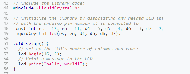
as far as the LCD is concerned please take a look to the following link:
It's a description on how to connect a 1602A LCD to an UNO board. In any case, should you need to change the pins assignment, you can follow the instructions reported therein.
The line of code where you configure the LCD pins seems to me wrong (no I2C should be referenced and the order of parameters seems messed).
In addition to that, in your Setup function you shall initalize the LCD with a line of code like: lcd.begin(cols,rows);
The following part of the code can be simplified as follows:
if ((switchState = digitalRead(switchPin)) == HIGH) on_off = '1'; else on_off = '0';
One "side comment" is: typically, to avoid spurious bouncing of the switches, it's better to select the input configuration as INPUT_PULLUP, this will enable the internal pullup resistor of the relevant input port. Obviously this leads to an "active_low" signal, but this is just a matter of software logic, while the benefit is to have a higher noise rejection.
A line which is not clear is also the following::
"receivedChar = on_off;"
why you overwrite the value received by the BT with the value previously set by the input switch ?
So, before going further in your logic, please take a moment to check that area of your code.
Cheers.
NNow I should have it fixed and I shouldn't have any more problems. Thanks very much to everyone 
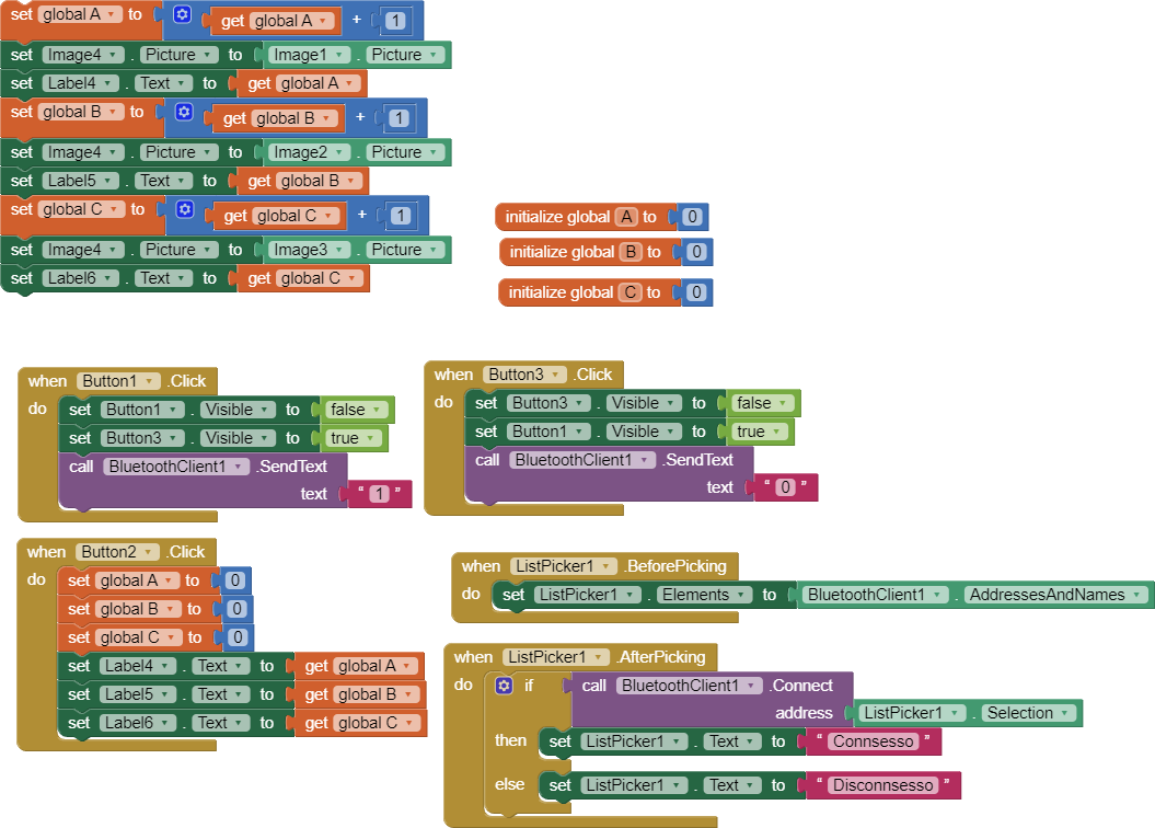
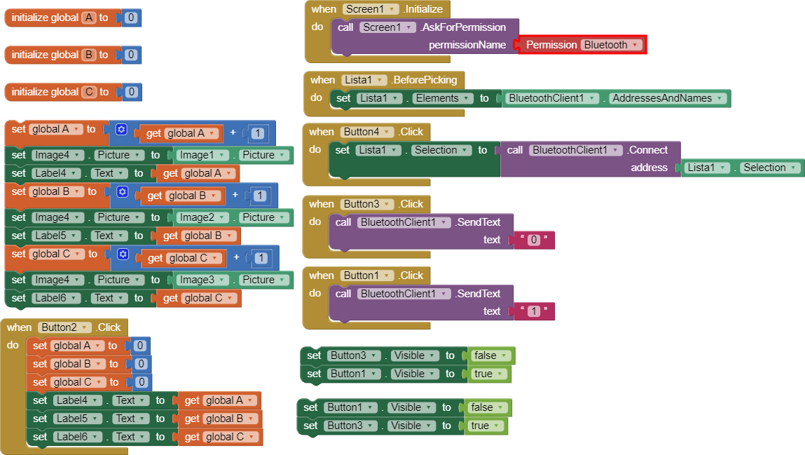
I trolled, I don't know how to get information from arduino/hc-05 to the app. It must receive three values that correspond to three figures and when it sends the signal it must increment its counter. Furthermore I have to put 2 timers, the first from when it is started and the other must be from when the last signal of the figure arrived. The blocks I have placed so far are these:
edit: The Arduino program is
(the program is incomplete as it is LCD and transmission of the 3 values and therefore the 3 shapes):
#include <SoftwareSerial.h>
const int switchPin = 12;
const int redPin = 10;
const int greenPin = 11;
const int pinMotor1 = 8;
const int pinMotor2 = 9;
const int pinS1 = A5;
const int pinS2 = A4;
const int pinS3 = A3;
const int rs = A0;
const int en = 13;
const int d4 = 2;
const int d5 = 3;
const int d6 = 4;
const int d7 = 5;
int switchState = LOW;
char on_off = '0', receivedChar;
SoftwareSerial bluetooth(6, 7);
void color(unsigned char red, unsigned char green, unsigned char blue)
{
analogWrite(redPin, red);
analogWrite(greenPin, green);
}
void setup()
{
pinMode(switchPin, INPUT);
pinMode(pinMotor1, OUTPUT);
pinMode(pinMotor2, OUTPUT);
Serial.begin(9600);
bluetooth.begin(38400);
}
void loop()
{
int currentSwitchState = digitalRead(switchPin);
if (currentSwitchState != switchState)
{
switchState = currentSwitchState;


if (switchState == HIGH)

{

  on_off = '1';

}

else

{

  on_off = '0';

}

Serial.print("Switch state: ");

Serial.println(switchState);

Serial.print("on_off value: ");

Serial.println(on_off);
}
if (bluetooth.available() > 0)
{
receivedChar = bluetooth.read();

Serial.print("Carattere ricevuto: ");

Serial.println(receivedChar);


if (receivedChar == '1')

{

  on_off = '1';

}

else if (receivedChar == '0')

{

  on_off = '0';

}
}
if (on_off == '1')
{
color(0, 255, 0);

digitalWrite(pinMotor1, HIGH);

digitalWrite(pinMotor2, HIGH);

Serial.println("Acceso");

int valoreS1 = analogRead(pinS1);

int valoreS2 = analogRead(pinS2);

int valoreS3 = analogRead(pinS3);

// Calcola la distanza in base al valore letto
float tensione1 = valoreS1 * (5.0 / 1023.0); // Converte il valore analogico in tensione (0-5V)
float distanza1 = 27.86 * pow(tensione1, -1.15); // Formula empirica per convertire tensione in distanza
// Calcola la distanza in base al valore lettofloat tensione2 = valoreS2 * (5.0 / 1023.0); // Converte il valore analogico in tensione (0-5V)
float distanza2 = 27.86 * pow(tensione2, -1.15); // Formula empirica per convertire tensione in distanza
// Calcola la distanza in base al valore lettofloat tensione3 = valoreS3 * (5.0 / 1023.0); // Converte il valore analogico in tensione (0-5V)
float distanza3 = 27.86 * pow(tensione3, -1.15)-5; // Formula empirica per convertire tensione in distanza
if (distanza1 < 10 && distanza2 < 10 && distanza3 < 10)
{
if (distanza1 > 1 && distanza2 > 1 && distanza3 > 1)

  {

      int p1=p1+1;

      bluetooth.write(1);

  }
}
// Stampa la distanza sulla console seriale
Serial.print("Distanza1: ");
Serial.print(distanza1);
Serial.println(" cm");
Serial.print("Distanza2: ");
Serial.print(distanza2);
Serial.println(" cm");
Serial.print("Distanza3: ");
Serial.print(distanza3);
Serial.println(" cm");
}
else
{
color(255, 0, 0);

digitalWrite(pinMotor1, LOW);

digitalWrite(pinMotor2, LOW);

Serial.println("Spento");
}
delay(1000);
}
/*int countObjects() {
// Simula la lettura da un sensore infrarosso
// Puoi personalizzare questa logica in base al tuo sensore reale
return random(1, maxObjects + 1); // Aggiunto 1 per ottenere un numero tra 1 e maxObjects inclusi
}
bool shouldProducePackage() {
return (objectCount[0] + objectCount[1] + objectCount[2]) >= 10;
}
void displayTotalPackages() {
lcd.clear();
lcd.print("Confezioni totali:");
lcd.setCursor(0, 1);
for (int i = 0; i < maxObjects; i++) {
lcd.print("Oggetto ");

lcd.print(i + 1);

lcd.print(": ");

lcd.print(totalPackages[i]);

lcd.print(" ");
}*/
Dear @minalbero,
there are still some issues in your approach.
If you want to ha a full-duplex coom's between the app and Arduino, you shall enable your app to receive BT messages when they arrive. To di so, you shall use a clock (a timer) that polls the BT input buffer often enough to be capable to catch characters as they arrive. Typically I use a 10 ms clock which verifies if any character has been received. If not, it exits immediately, if yes, it stays thare until the last character has been fetched.
The following image shows only the above. rationale; I don't have reported the asking for permission blocks that you shall maintain in yours.
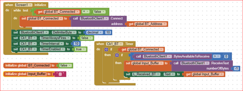
Please pay attention to the "-1"number of characters: this means thet until the ending transmission character Linefeed (i.e. 0x0A or 10 decimal) is received, the ReceiveText block remains there waiting for any new character coming from the BT.
To accomplish this method, on Arduino side, the transmission to the BT shall be ended with a Serial.println(); instruction. So, if you transmit only one character it shall be done as Serial.println(character_to_be_sent);
A good example is (as always  ) on @Juan_Antonio's web site KIO4.com.
For instance this link:
Bluetooth. App Inventor. Comandos AT. Monitor Serie.
leads you to a couple of codes (both AI2 and Arduino) in which you can see how to perform a complete bidirectional communication. One step beyond.....