Hello, I am new here. I am still not entirely understanding how it all works, I am just speechless how much I achieved in so little time. Awesome!
I needed an app to interact with an Arduino by sending characters which Arduino would interpret as commands. Works like a charm.
The Arduino in turn sends back coordinates (a character and a number). I found a video tutorial of a calculator and used the blocks accordingly (a label would get asigned another text upon receiving a Serial input). This does not work in my case. The label never changes. When I connect my Arduino with my computer, I see the correct coordinates. I see the Tx led blink only if the computer is connected, not if my phone is (via USB OTG). Why would my Arduino not send anything to a phone (btw, it is a Leonard clone), but to a computer? Is that more of an Arduino problem, then?
I would also like to know how my app knows what to make of a serial data stream - I cannot find any variable declaration anywhere. In the video I saw, the author declared floats only in the Arduino code. That looks like Android would by default always interpret incoming data as floats, but that can't be right, can it?
In my Arduino sketch I tried both Serial.write, and Serial.print(character) and Serial.println(number), but no success.
I also do Read.Serial every 500 ms and change the labels text only if new data is available, as indicated in the delimiter article.
Thanks very much for any hints, I tried to solve it for a couple of days, but I am at the end of my wits. I understand that a connection to Arduino (with something boring like a USB cable instead of BT) is only a tiny subset of the possiblities available with AI, but maybe someone has an idea.
Cheers
Sebastian
Dear Sebastian,
it's a bit difficult to help you effectively, without more details on what is your Arduino code and your AI2 blocks. Could you post your code(s) : Arduino and AI2, so the community can have a look on them and help you successfully.
BTW is your OTG cable supplying enough power to the Arduino board ? Are the LED's of the board lighting up ? For example I've tried with a Samsung Grand Neo, and it does not light up the Arduino board, while with a Xiaomi MI5+ it works. So maybe in your phone you don't have the OTG function or it is not enabled. Have you checked it ?
Best wishes.
Ugo.
Dear Ugo,
yes, you are absolutely right, my bad, I should know better. So, before I provide the codes, some additional diagnostics I did:
-
I checked if my phone (Samsung A3 6) can do OTG. One website said it couldn't. But it actually does everything I want it to do except the coordinates. I checked with a spare Samsung phone, which can do OTG, and it behaves just the same. I use a OTG adapter I bought cheaply on Aliexpress.
-
As recommended somewhere, I installed Serial USB Terminal by Kai Morich. On both phones it receives the proper feedback from my circuit. I also saw that other than running on the app, when the phone/arduino combo collaborates, the TX LED blinks. SO if I connect the app, arduino doesn't send anything, but if I connect the Serial USB Terminal or the Arduino IDE, the board works properly. What's the difference?
-
And yes, the board works properly. As it does not rely on an app, but also works stand-alone, I can say that it basically does the same. Because again, the buttons and all from the app work, just the feedback is missing. Power draw is 30 mA on USB.
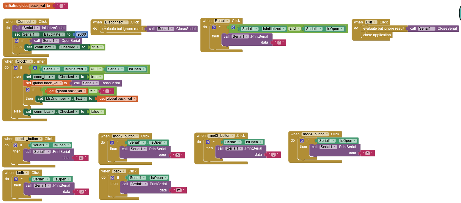
OK, here it comes:
I hope it is readable. All the buttons to send a, b, c, d, p, m, and r work just fine, Exitbutton as well. Connect and disconnect, too.
My Arduino sketch is rather bulky. Basically, the feedback happens here in a separate function:void count_to_coord()
{
if (count < 61)
{
y = (count % 12);
z = 'E';
if (count < 49)
{
y = (count % 12);
z = 'D';
if (count < 37)
{
y = (count % 12);
z = 'C';
if (count < 25)
{
y = (count % 12);
z = 'B';
if (count < 13)
{
y = (count % 12);
z = 'A';
}
}
}
}
}
if (y == 0)
{
y = 12;
}
Serial.print(z);
Serial.println(y);
}
So instead of doing a division, I iterate through the ifs until the count number is bigger, so the last assigned values will stick. Then, I avoid the 0 coordinate, and I send it out via Serial.print. z is a char, y is a byte. count is incremented with every p (as in "plus") command, or decremented by m (as in "minus").
As mentioned before, when connected to a phone with the app or the companion, I do not see the Arduino's Tx LED light up. I do see that when connected to a computer or a phone with the USB Sertial Terminal. The Arduino is a selfmade Leonardo clone, but I developed the count_to_coord bit with a Chinese Arduino Micro clone.
I hope this helps. Thanks for any tip.
Cheers
Sebastian
I guess that your timer is initialized by settings in the properties.
Leonardo and Micro uses a 32U4 chip and cdc_acm communication protocol. I think you must set Rts=1 to enable transmit from the 32U4. This signal is not available in the built in serial component, so I recommend that you use my extension instead as discussed here: Using serial with FTDI
You can find the extension and some documentation here:
The functions of this extension will hopefully be included in AppInventor in the future.
I hope this will solve your problems.
Good luck
Rkl099
I used a version (not the latest) of the extension of @rkl099 and it worked for me.
Outstanding! Now I got what I need, thank you so much, rkl099! Yes, this should be included in the future.
Thanks for all the answers. I like it here, I guess I will stick around.
Cheers!
Recently, @ewpatton asked you if the extension is ready to roll out to app inventor.