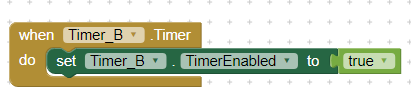
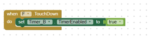
The above code will never run at all, if TimerEnabled isn't set to true. When ClockComponent.Timer will only be called when TimerEnabled is true.
You will also need to set the TimerInterval (in ms):
I red the clock component documentation using given link
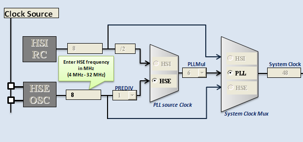
Above image is showing microcontrolller timer block diagram. So I need to further confirm that,....when Timer is on in the MIT App Inveterate, Does it communicate with the real hardware timers like above image is showing
It won't, you will have to control it with said microcontroller somehow (sorry, I'm not the best at microcontrollers). Maybe if you're using Arduino, you could communicate between them with a Bluetooth module (you can search for @Juan_Antonio's tutorials on this community).