Dear all,
while continuing to experiment the power of MIT AI2, I have written a piece of code to connect my car's OBDII line using an ELM327 interface to a tablet via a BT link..
In the annexed aia you'll find the app, and in the assets sub-directory (open the aia with 7zip) a docx file that contains a few pages on the sw architecture (written in my low level english ).
It's not an elegant and refined app, but it works, so I hope that it could be of some help for someone who wants to play with CANBUS.
Enjoy !!!
PS. : last but not least ... many thanks to TAIFUN and KEN for their powerful extensions, as usual !!!
This is great stuff.
If you don't mind, I'll open up the contents for easier reading on the board ...
24th/June/2020
CANBUS DIAGNOSTIC PROTOCOL CONNECTION WITH ELM327 AND MIT AI2 APP
--- FOREWORD ---
This piece of code is not a complete APP. It’s just a way to show how to connect a car ECU (Electronic Control Unit) by means of a CAN interface (the diagnostic interface). It assumes a little knowledge on Bluetooth and CAN protocols (not really so much!). There are many App’s capable of a complete diagnose of a car status, but this code is just to verify if we are capable to do the same. Anyone can go further improving this code which is just an exercise. Hoping it can help someone.
--- HW REQUIRED ---
ELM327 CAN to Bluetooth interface: from 5$ on Amazon .
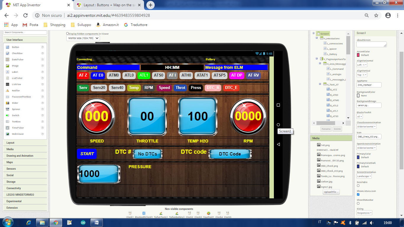
Any 8” display tablet (if you want to use my Screen1 layout, see below, otherwise you can re-arrange it according to your available device)
--- MAN IN THE MIDDLE ---
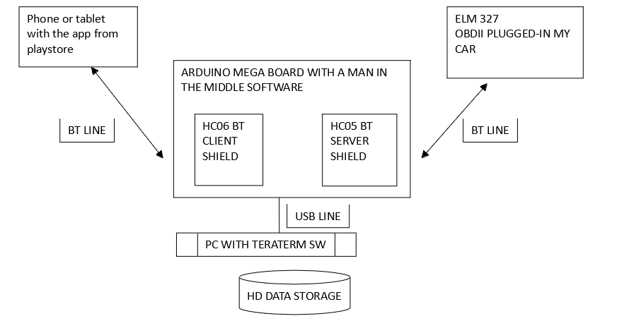
I have been able to discover the commands sequence used to wake up my car’s ECU and to put it diagnostic mode by putting a sniffer (a “man in the middle”) between an already done (free) app, available on the Playstore, and the ELM327 connected on the OBDII socket of my car.
In this way I have recorded and analyzed the commands, so to replicate them with my app.
The scheme is here below:
The Arduino SW (written by me) is simply a “sniffer”: any character received by the phone is sent both to the ELM327 and to the PC, where it is stored on the HD. Any character received by the ELM is sent both to the phone and to the PC where it is stored. In this way I have catched all the commands sent by the phone to the ELM 327 (to my car) and all the responses sent by my car to the phone. The Mega board is necessary because we need 3 serial lines (2 for the BT’s and one for the USB toward the PC)
Once stored the commands and their responses on the HD, in a file, I have had the possibility to read them. They are ASCII characters, so easily readable. You don’t need to do the same. I did it just to understand which could be the commands sequence between the app and the car. Once understood the commands and their responses I have written my app.
--- WHY SO MANY CLOCKS ---
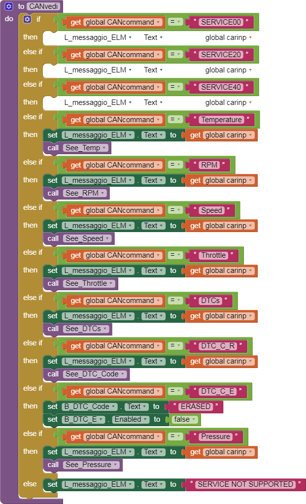
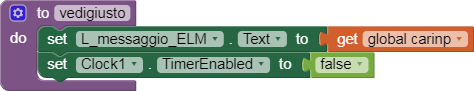
Clock1= performs the data receiving from ELM327; it calls the “show data procedure(s)”. It detects if an AT command or CAN command has been received. In the first case it shows the modem commands (AT commands) and their responses. In the second case it calls the procedure that shows CAN data. It is enabled each time a command is sent by the app to the ELM327, and it is stopped whenever a good answer is received.
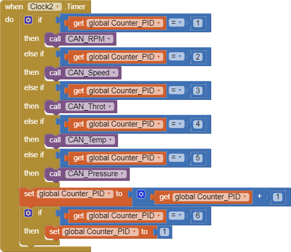
Clock2 = a scheduler that performs a timely sending to the ELM327 of the CAN commands. It is started at the and of Clock4 and repeats forever until the STOP button is pressed (Note: the START button toggles its label to STOP, once started. It toggles back to START if pressed while it shows STOP).
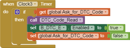
Clock3 = to ask the ELM327 for Data Trouble Codes retrieval from car ECU. Necessary to allow the ECU to read DTC’s and to have tham ready for display. Tested only in a simulated environment, not on the real car.
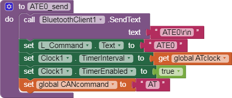
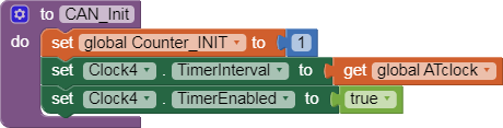
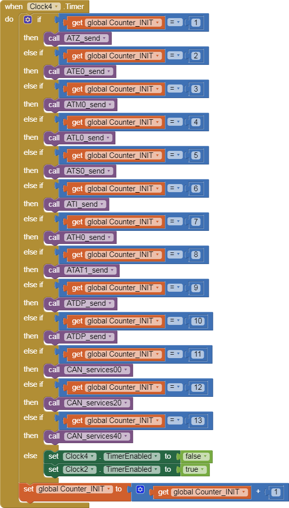
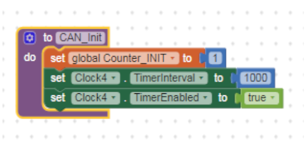
Clock4 = a scheduler to send AT commands in sequence to to initialize the ELM327 and the CAN communication with the car ECU. Started by the START button. It fires many times until the last command in the sequence is called. Then it disables itself.
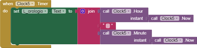
Clock5 = simply shows hours and min’s onto display. It fires at any second.
--- BT RECEIVING PHYLOSOPHY ---
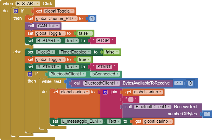
Once activated the BT client, the app sends a request (via BT) to the ELM and waits for the answer. It waits until a complete response has been collected. Any response is terminated with a “>” character, so a -1 is set as a receiving buffer length and it waits until the “>” is received. To avoid to leave characters in the buffer, the receiving steps are repeated until no new characters are received, in the meanwhile (see Clock1). An empty message is also discarded. A CAN response is checked to be the one related to the command: in other words if the command was 01 05 the only accepted answer is 41 05 (any other answer id rejected until a true 4105 is received: no timeouts: “just a quick andirty software”) .
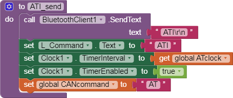
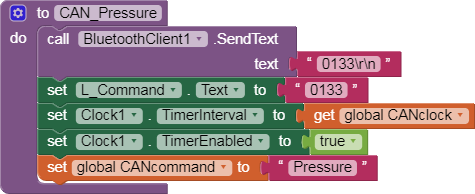
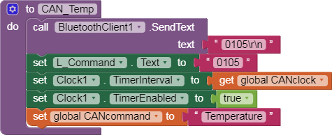
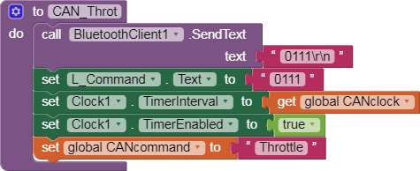
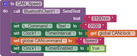
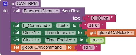
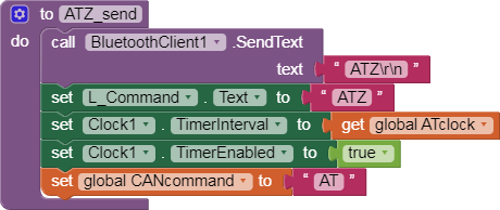
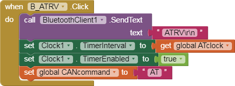
The coloured buttons send the respective command once (by hand ).
They are put in a sequence (from left to right) as they were sent by the ELM327 automatically.
The button START sends the complete sequence automatically in order to initialize the coomunication toward the car ECU
The CAN protocol currently selected is KWP @250 Kbps (#5 in ELM327 list) because that’s the one of my car. Most probably yours is another one, just check it with an automatic search of the ELM327.
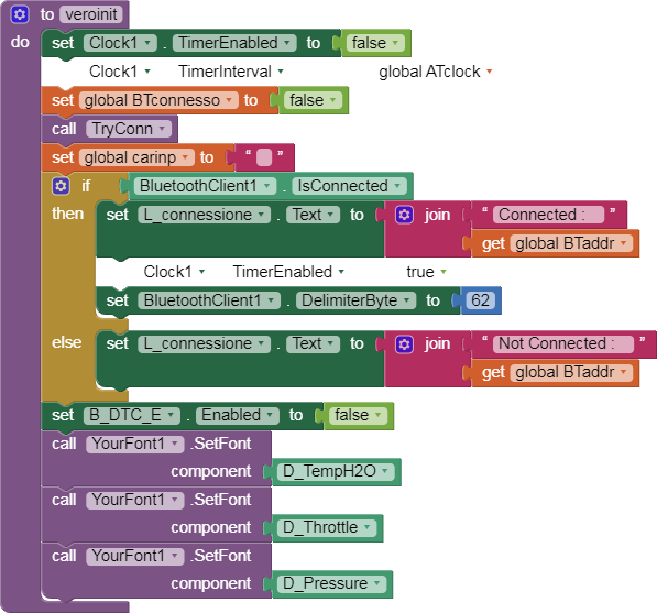
The BT address is fixed (my ELM327 one): simply change it with the address of your ELM327 interface box.
Take care of the interframe time (some 250 ms typically). It can be suitably tailored with the transmission speed of your car (i.e a CAN @500 Kbps). Don’t be too much fast (too short interframe time) otherwise it does not work. Once found the best compromise between updating rate of the screen and the communication capability of your car you can, leave it.
A complete document on ELM327 use and commands is embedded here.
--- THANKS ---
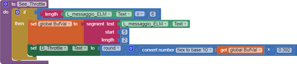
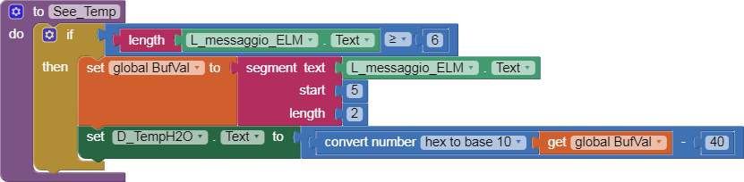
Thanks to KEN: Don’t care if the throttle, temperature and pressure digits seem to be left aligned, the alignment becomes correct once the app is running because the seven segment font that I use in “your font” extension (KEN’s extension) aligns the characters a bit on the right, so I need to offset them on the left in order to have them in the middle.
Thanks to TAIFUN: for his “keep screen on” extension. ELM327DS.pdf (467.1 KB)
Dear all,
I'm really pleased of your interest in my code
Whether someone needs the Arduino code, just let me know, I will upload it.
It is really a trivial piece of software that mirrors the characters received from one of the three sources (BT#1; BT#2 and PC) between each other.
All the best..
PS in my blocks I use this convention:
B_xxxxx = Buttons
L_xxxxx = Labels
D_xxxxx = displays (sometimes I use buttons as displays because I can fill them with background images...)
H_xxxxx = Horizontal arrangements layout
V_xxxxx = Vertical arrangements layout
Labels without specific references are just Hor and Vert spacers to align other stuffs on the screen
BTW: TIMAI2, I believe that on your wonderful classic car there isn't a CANBUS
//========================================================================================
// 24/06/2020
// OBDII sniffer Rev 0.0
// Chunk of code to allow the readings between two BT shields and to store the data on
// a hard disk. Needs an Arduino Mega because it uses three serial lines
// Serial 1 links the HC05 shield then the ELM327 (the OBDII)
// Serial 2 links the HC06, the tablet
// Serial links the PC (Arduino standard USB connection)
// On Teraterm is com9 in my today's serial ports list
// The HC05 must be set as Master toward ELM327. The ELM327 BT address shall be set
// in the HC05 setup with AT commands. to do that use the AT BIND command
//========================================================================================
#include <avr/io.h>
String command = ""; // Stores response of the HC-06 Bluetooth device
long baud;
long i;
char carinp;
//========================================================================================
void setup()
{
// Open serial communications:
Serial.begin(115200); // toward PC
Serial1.begin(115200); // master toward HC05 and ELM
Serial2.begin(115200); // toward HC06 and tablet
}
carinp = 0; // initializes the input buffer to empty (1 character only)
if (Serial1.available()) // from hc05 OBD2
{
while(Serial1.available() )
{
carinp = Serial1.read(); // gets the character received from ELM327
Serial2.print(carinp); // sends it to the HC06 i.e. the tablet
Serial.print(carinp); // and sends it to the PC as well
}
}
carinp = 0;
if (Serial2.available()) // from Hc06 Tablet
{
while(Serial2.available() )
{
carinp = Serial2.read(); // gets the character received from Tablet
Serial1.print(carinp); // sends it to the HC05 i.e. the ELM327
Serial.print(carinp); // and sends it to the PC as well
}
}
carinp = 0; // just to allow the PC (i.e. Teraterm) to send commanda to the ELM, if useful
if (Serial.available()) // any characters from PC ?
{
while(Serial.available() )
{
carinp = Serial.read(); // yes, get it from PC
Serial1.print(carinp); // sends it to ELM327
}
}
}
Dear all,
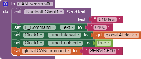
I really do apologise for this "bug", but I have left in the CAN_init block a "wrong" Clock4 timing (100ms instead of 1000ms) so please discard the previous value and use the new one, as per annexed .png.
Sorry ....
Cheers.
Interesting topic. Is arduino really necessary here? Could we get rid of the arduino and connect the phone directly to the elm? Or get rid of elm, add can module to arduino and connect arduino to can network without elm.
Dear @Patryk_F,
thanks for your interest. As a matter of fact both solutions are practicable. it depends how old is the car
I tell you the tale...
In my original post I was saying that I have used two Arduino HC05's: one server toward the ELM and one client toward the phone (pad) because I needed to "discover" the exact sequence used by the app running on my phone to open the diagnostic session toward my car, and to ask for services (to this purpose i used OBDcheck, but you can use any free app found of the playstore) . In this way, by using the Arduino board + 2 HC05's as a "man in the middle" I've been capable to show on the Arduino monitor (the PC screen) the sequence of messages sent by the app. From that moment onward the Arduino is not required anymore. I've just replicated the sequence on my pad (phone) with a AI2 code and that's all. Of course, once discovered the starting sequence and the services (like: read speed/RPM/H2O temperature/inlet pressure,. and so on), is up to you to make your own user inteface as cute as can be. The advantage of using the ELM is that it knows the syntax of the KWP2000 or UDS protocols (the vehicles' diagnostic protocols) and gives back the values already in a "readable form".
This is therefore applicable with OBDII vehicles with KWP2000 or UDS protocols on CAN bus (as of today : 98 %). If a car does not feature such protocols, like my old Renault Megane convertible that is using a proprietary X85 protocol (by Siemens) I use, instead of an ELM (that does not include such specific protocol), an Arduino with a ISO9141 (K-L line) hardware interface (it's not a CAN either !!!). Just a few components that I put together, but mandatory because the K-L line is an old HW standard, born when the CAN wasn't yet the monopolist of busses.
At the very end:
=>ELM + phone with AI2 code for cars featuring OBDII on CAN (and KWP2K or UDS after having "sniffed" the commands with the man in the middle)
=>Arduino + HW interface to vehicle + BTHC06 + phone for cars not featuring KWP2K or UDS on CAN (i.e. ISO9141 or even older )
If I've been not clear enough, or you need some more details, I'll be happy to continue..
Cheers, Ugo.
PS I forgot to say: if you have (on an official document from a car maker) the message map of a vehicle, you should not need the man in the middle, but though the KWP2000 and the UDS protocols are "standard", it is very difficult that you can interface a vehicle without troubles... car makers always change one bit here and there, just to avoid that everybody can develop a diagnostic tool free......


 )
)