I known it send x/y axis location data, but by what type? raw data? does it send ‘x’, 'y' character?
Thanks
Adam
diagram from: http://ai2.appinventor.mit.edu/#6659773495115776
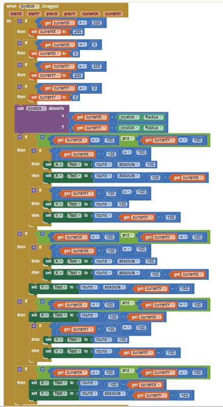
The Block you posted appears to be a Canvas renamed joystick. The code addresses Canvas x,y locations.
See Creating Animated Apps to understand how the Canvas is arranged. See also the Canvas documentation.
SteveJG, thank you.
The files all helpful.
Can you simply tell me how the receiver know which data is 'x', and which data is 'y'?
Thanks.
Alan Jackson has a similar app https://sites.google.com/site/alanjacksoncsportfolio/app-inventor-joystick . Perhaps his explanation for his similar app will help.
The x value is posted in a what is probably a Label renamed X and y is posted in a Label probably renamed Y.
The link to the diagram you posted can only be read by you Adam so I am guessing from the Block construction.
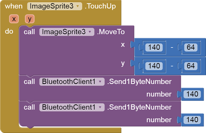
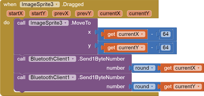
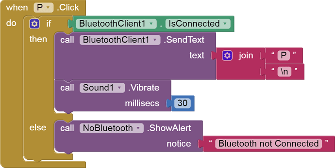
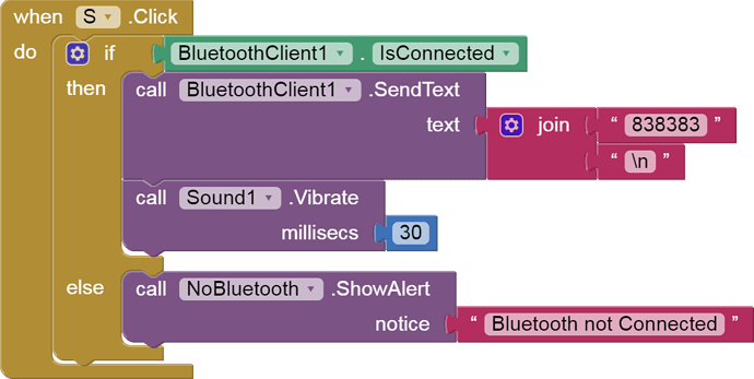
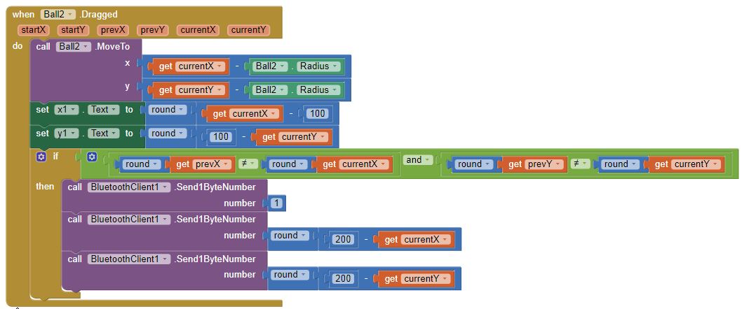
No. It sends numeric byte values, from these blocks:
That means trouble for the receiving code, which you do not supply, because it requires exact timing and byte counting to know which byte is x and which is y, since they arrive alternately xyxyxyxy.... If you slip a gear, all your xs will be ys and vice versa.
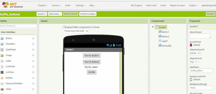
To make the scheme even worse, this code send text from 2 buttons:
Further comment is pointless without the Arduino code, aside from recommending an all-text approach.
Thank you ABG.
I attached the Arduino code here and see if its helpful to figure out why the Arduino can't receive the correct data?
#include <SPI.h>
#include "CONFIG.h"
const int Start_Relay = 12;
const int Stop_Relay = 13;
const int X1_Relay = 40;
const int X2_Relay = 41;
const int X3_Relay = 42;
const int X4_Relay = 43;
uint8_t xAxis = 140, yAxis = 140;
uint8_t x = 0;
uint8_t y = 0;
char command;
void setup() {
// put your setup code here, to run once:
Serial.begin(115200);
Serial1.begin(9600); // Default communication rate of the Bluetooth module
SPI.begin();
Serial.println("Setup complete");
Serial.print("File : "), Serial.println(FILE);
Serial.print("Date : "), Serial.println(DATE);
pinMode(Start_Relay, OUTPUT); //START Relay
pinMode(Stop_Relay, OUTPUT); //STOP Relay
digitalWrite(Start_Relay, LOW);
digitalWrite(Stop_Relay, LOW);
}
void loop() {
// put your main code here, to run repeatedly:
Bluetooth();
Motor();
}
void Bluetooth()
{
// Read the incoming data from the Smartphone Android App
while (Serial1.available() >= 2) {
command = Serial1.read();
delay(300);
Serial.print("command =");
Serial.println(command);
}
if (command == 'S') { //uP_button 'A', A -- 65, ORANGE-3
digitalWrite(Start_Relay, HIGH); //set up_button
delay(1000);
// digitalWrite(Start_Relay, !digitalRead(Start_Relay)); ////
Serial.print("command13 =");
Serial.println(command);
delay(5);
}
if (command == 'a') { //uP_button 'A', A -- 65, ORANGE-3
digitalWrite(Start_Relay, LOW); //set up_button
delay(5);
}
 if (command == 'P' ) {  //uP_button 'A', A -- 65, ORANGE-3
digitalWrite(Stop_Relay, !digitalRead(Stop_Relay)); //set up_button
delay(1000);
digitalWrite(Stop_Relay, !digitalRead(Stop_Relay)); ////
delay(5);
}
if (command == 'b' ) { //uP_button 'A', A -- 65, ORANGE-3
digitalWrite(X1_Relay, !digitalRead(X1_Relay)); //set up_button
delay(1000);
Serial.print("command49 =");
Serial.println(command);
if ((unsigned long)(millis() - previousMillis5) >= interval5) {
  previousMillis5 = millis();
}

digitalWrite(X1_Relay, !digitalRead(X1_Relay)); ////
delay(5);

if ((unsigned long)(millis() - previousMillis025) >= interval025) {
  previousMillis025 = millis();

}
}
if (command == 'c' ) { //uP_button 'A', A -- 65, ORANGE-3
digitalWrite(X2_Relay, !digitalRead(X2_Relay)); //set up_button
delay(1000);
Serial.println("command49 =");
Serial.println(command);

if ((unsigned long)(millis() - previousMillis5) >= interval5) {
  previousMillis5 = millis();
}

digitalWrite(X2_Relay, !digitalRead(X2_Relay)); ////
delay(5);

if ((unsigned long)(millis() - previousMillis025) >= interval025) {
  previousMillis025 = millis();

}
}
}
void Motor()
{
// Read the incoming data from the Smartphone Android App
while (Serial1.available() >= 2) {
x = Serial1.read(); //WAS: xAxis = Serial1.read();
delay(100);
y = Serial1.read(); // WAS: yAxis = Serial1.read();
delay(100);
xAxis = x;
yAxis = y;
Serial.print("xAxis48=");
Serial.print(xAxis);

Serial1.print("yAxis51=");
Serial1.print(yAxis);
}
delay(10);
// Makes sure we receive corrent values
if (xAxis > 130 && xAxis < 150 && yAxis > 130 && yAxis < 150) {
Stop();
}
if (yAxis > 130 && yAxis < 150) {
if (xAxis < 130) {
  turnRight();
  motorSpeedA = map(xAxis, 130, 60, 0, 255);
  motorSpeedB = map(xAxis, 130, 60, 0, 255);
}

if (xAxis > 150) {
  turnLeft();
  motorSpeedA = map(xAxis, 150, 220, 0, 255);
  motorSpeedB = map(xAxis, 150, 220, 0, 255);
}
} else {
if (xAxis > 130 && xAxis < 150) {

  if (yAxis < 130) {
    forword();
  }
  if (yAxis > 150) {
    backword();
  }

  if (yAxis < 130) {
    motorSpeedA = map(yAxis, 130, 60, 0, 255);
    motorSpeedB = map(yAxis, 130, 60, 0, 255);
  }

  if (yAxis > 150) {
    motorSpeedA = map(yAxis, 150, 220, 0, 255);
    motorSpeedB = map(yAxis, 150, 220, 0, 255);
  }

} else {

  if (yAxis < 130) {
    forword();
  }
  if (yAxis > 150) {
    backword();
  }

  if (xAxis < 130) {
    motorSpeedA = map(xAxis, 130, 60, 255, 50);
    motorSpeedB = 255;
  }

  if (xAxis > 150) {
    motorSpeedA = 255;
    motorSpeedB = map(xAxis, 150, 220, 255, 50);
  }
}
}
analogWrite(enA, motorSpeedA); // Send PWM signal to motor A
analogWrite(enB, motorSpeedB); // Send PWM signal to motor B
}
void forword() {
Serial.println("forword");
digitalWrite(in1, HIGH);
digitalWrite(in2, LOW);
digitalWrite(in3, HIGH);
digitalWrite(in4, LOW);
}
void backword() {
Serial.println("backword");
digitalWrite(in1, LOW);
digitalWrite(in2, HIGH);
digitalWrite(in3, LOW);
digitalWrite(in4, HIGH);
}
void turnRight() {
Serial.println("turnRight");
digitalWrite(in1, HIGH);
digitalWrite(in2, LOW);
digitalWrite(in3, LOW);
digitalWrite(in4, HIGH);
}
void turnLeft() {
Serial.println("turnLeft");
digitalWrite(in1, LOW);
digitalWrite(in2, HIGH);
digitalWrite(in3, HIGH);
digitalWrite(in4, LOW);
}
void Stop() {
digitalWrite(in1, LOW);
digitalWrite(in2, LOW);
digitalWrite(in3, LOW);
digitalWrite(in4, LOW);
Serial.println("stop");
}
Your code confirms my suspicions that you are trying to alternately receive binary and text values in the same data stream. That's hard to do.
I went looking for samples that send delimited text to an Arduino from Ai2, that have the Arduino extract numerical data from the arriving text.
Unfortunately, I came up empty.
Maybe one of the C experts on this forum has a sample for you?
Thank you ABG.
yes it is sending the Joystick's x/y location data and the button data mixed.
I've tested the code for Joystick and for button alone works well, but no work when mixed. don't know why?
would you please explain the below block?
what 0b00000000 mean? is it mean a address in Phone or Arduino?
how and where to get this data?
Best to you.
The leading 0b tells AI2 and us that the remaining data is to be interpreted as binary digits, in this case eight zeroes, just enough to fill an 8 bit unsigned byte. If you know your binary, that's just 0.
(It has been said that there are 10 types of people in this world, those who know binary and those who don't.)
The 0b00000000 constant appears in the init of a variable named send_byte, so I would guess that the original author's intention was to send it as a byte.
To proceed further in this endeavor, you need a good reference on the Arduino C data types, and the C commands to convert from one type to another type, along with the C commands to transmit and receive different data types.
(I don't have one.)
For example, I have seen C commands Write() and print() that deal with data types differently. Find a link where that is explained.
Thank you ABG.
Would you please explain the below picture with more detail? sorry of a newbie.
- there do have 'x', 'y', put there in the call Ball2 block, does the 'x' 'y' be sent to Arduino before the data sending?
- does the purple block 'call Ball2' take the real 'x' and 'y' value automatically? because the return block have the same definition?
- set 'x1' Text to round to what? if the currentX= 87, what's the result?
- is the number '1' a sign to mark the number sending after?
Who is giving you these blocks, and why can't they explain them to you?
I don't understand your question.
Maybe you are asking if this would be a good place to send the Arduino a warning that it is about to receive an x value and a y value?
Maybe.
I don't see any 'return block' so I am not sure what you mean by that.
Here is how to read the x and y inputs to that call Ball2 MoveTo block...
If you look in the Designer attributes of Ball2, you should see an attribute that tells you if the X,Y values of that Ball are either
- for the upper left corner of the ball, or
- for the center of the Ball.
The currentX and currentY variables are receiving their values from the dragged event. I know this because I see them sitting in the 5th and 6th positions at the list of variable definitions in the golden Ball2 Dragged event frame. Those act like init blocks, capable of popping up get and set blocks when you hover the cursor over them. Do you see how they are the same name as the variables going into the Ball2 MoveTo block? The author of these blocks has decided to nudge the Ball2 to the left and up while dragging, so its center is under the user's finger, rather than having it stick out to the SouthEast of his finger. I guess he has thin fingers, or the Ball is big.
The Dragged event does not move Ball2. You need the MoveTo block to make it move with your finger.
The AI2 round block rounds to the nearest whole number. (You can see a tool tip if you hover your cursor over a block in the Blocks Editor.) I am not convinced that was really necessary, because currentX and currentY might be coming back as whole numbers (px) from the drag event. (You could copy them into global variable or Label x1.Text to verify my guess.)
If currentX = 87, x1.Text would show -13, (which is 87 - 100).
Maybe, but it's not a good one. When the drag crosses coordinates (199,199) the values (200-199) will equal 1, and a sequence of three 1's will be sent, risking the receiving end losing track of which number 1 was meant to herald the imminent arrival of x and y.
It gets worse. This code is sending 1ByteNumbers. You should be asking, What are the minimum and maximum allowed values of a 1ByteNumber? Somewhere around -127 to +127, give or take a leftover 1 on the negative end of the range. Why do I mention this? Consider how big Canvas1.Height and Canvas1.Width are, and the center (200,200) of the coding range for the X,Y Ball coordinates. You will find yourself trying to send 1ByteNumbers that can't fit your required values, like -199.
Read this tutorial on data types ...
Thank you ABG.
- I found this Blocks online, and I am not be able to contact the author now;
- there are 'x', 'y' letters on the first Purple block, my question is: is the 'x' just indicated the value 'get currentX' belongs to x? will the 'x' be send together with the currentX?
- both the x and y = get currentX(Y) - Ball2 Radius, I don't see how x and y get their real value? any calculation included in the currentX function?
I'll follow the link you provided for the others.
Thank you so much for help.
See the free book in
Great.
Thank you ABG.
