First of all i would like to thank everyone reads this post. I am pretty sure that this post would look weird to most of you as it was to me. I am trying to turn on a small aquarium pump through sms. The pump runs on AC current. So, my connection goes as follows
Cell phone -> OTG -> Arduino -> Relay -> Pump
Obviously, one end of the relay is connected to AC main supply and the other end to pump. As soon as I send sms "ON" from other cell phone, app reads the message and send "1" to arduino through serial communication. Arduino will turn on relay
Everything works well when I tested with relay not having mains power supply. When I turn on mains supply to make my pump running, an issue rises between arduino and app. I have to remove the OTG cable and re-plug to establish the serial communication again. It stuck at the point of "Opening" the serial communication. I tried this circuit even in a bread board, but result is same
Step to recreate my issue
Turn on AC power supply to relay
Open the app
Click "Initialize" button
Click "Open" button -> stuck with button highlighted as if I am long pressing
if I omit step 1, its working so good and nice. It is not the issue only with MIT app, I even tried ArduinoDroid to send "1" manually. It gets stuck when I turn on AC power to relay. I couldn't make serial communication with arduino
I would appreciate if anyone has work around for this issue
You probably need an AC mains lowpass filter on your power supply or get another power supply for the pump. The pump or the relay or the power supply is creating an electronic spike creating interference. You can buy or make a low pass filter that might correct the problem. Alternatively power from a battery.
This issue appears to be an electronic interference issue related to your inexpensive power supply, arcing of your relay which possibly momentarily disrupe your Arduino (which is also plugged in); not an issue with App Inventor.
Thank you very much for your reply. I am trying to figure out this issue for past two weeks. I thought something like this should cause the issue. But I tried few alternatives in the past
One such alternative is establishing serial connection through laptop. It is working fine. If I turn on main supply after I open serial monitor, I am still able to send "1" and "0" successfully. I tried this multiple times. Its working fine
I tried optocoupler 4N25 to drive relay. The result is same issue (with mobile phone)
I would also like to highlight one important point here. When I turn on power supply, it is directly from wall socket. It is my house main power which runs all the house appliances. More importantly when I turn on my wall socket, AC power is not at all in the closed loop. NO pin of relay is still not in contact with COM of relay. The issue is not starting when I turn on pump. It's just turning on wall socket which creates issue. So, I would like to understand how sparking would happen in this case?
I am pretty sure that it is not due to App inventor. I faced same issue with Arduinodroid.
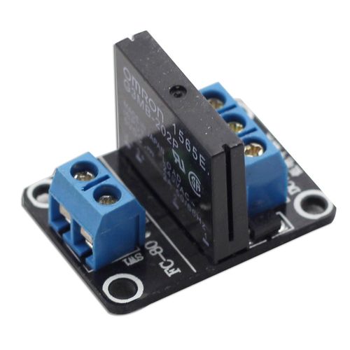
A small spark at relay contacts can cause a momentary electromagnetic field (EMF) event. Is this causing your issue? Maybe. What kind of relay is it? Is it a relay with a primary coil using 12 volts; 110 or 220 volts to close the contacts. Interference and a small spark may be caused when using a relay as the contacts connect momentarily; it stops when the relay latches. This is especially true if the relay has a high voltage primary coil.
Is the power supply for the relay the 'mains' voltage or is the voltage converted by a small power supply that plugs into the wall socket?
If turning on the wall socket in turn turns on the power supply or the relay, you could have an issue.
My guess, the issue is created by turning on the relay. (either by arcing at the relay contacts or your wall switch)
It is 9 V at the primary coil and 220 V across NO and COM. The power supply is directly from wall socket. No extra special circuit between my socket and relay. Turning on the wall socket doesn't turn on anything. It just makes the AC power available till NO. Just this action causes issue. This is the most confusing part for me. Sparking at the wall switch could be a reason (though I find no reason for it to spark), but relay is not at all doing any task at that point
I have taken video of my issue. Notice the click sound at the relay when I send 0 and 1 when AC power is turned off. The small lamp will be replaced by pump in my project
Your 220 volt connection scares me. 220 can kill so be careful with that breadboard hook up.
Your video flits around like a butterfly. I couldn't get much from it.
Do you still have the issue when you use the bulb instead of the pump?
When you plug a relay into 220 mains power, you energize the solenoid. Usually connecting power to the relay latches the relay. Sometimes when the relay contacts meet there is a momentary burst of electromagnetic energy. If the power supply to your electronic toys is not filtered, the 'spark' created can cause a transient within nearby electronic equipment. Does the possible transient originate from flipping on the light switch or from the relay contacts or any of this at all. I certainly don't know. You can test if flipping the power switch is the problem by turning the switch on with the power supply not plugged in. Then plug the power supply cable into the mains socket. With the connections you have, I would be reluctant to do that because of potential shock hazard. None the less, if flipping the switch followed by plugging in the relay doesn't elicit the problem, the issue is the switch arcing. If you still have the issue, it might be something with the relay or using an unfiltered mains supply for your arduino and peripherals. I honestly don't know.
Regarding the emf that might be the result of a switch sparking; it is similar to the interference you hear on an AM radio signal during a thunderstorm. That increases every time there is a lightning strike and you get a static crash. Turn on a portable AM radio receiver near your set up and see whether you get a pop in the speaker when you switch your power on or energize the relay. Hear a noise and you might have fond the issue.
I don't have any toys like yours. My electronic experience comes from building and testing radio transmitters and receivers and power supplies. Emf, if that is the issue, could be affecting your Arduino momentarily. A small disruption might be enough to cause your issues. Hopefully someone who builds stuff similar to your project will provide some feedback to you. You might ask for help on an Arduino forum.
OR even better get a Solid State relay.
Benefits:
No relay coil to collapse therefore no spikes.
No relay contacts, therefore no EMF problems.
Totally silent operation.
Less current required to operate.
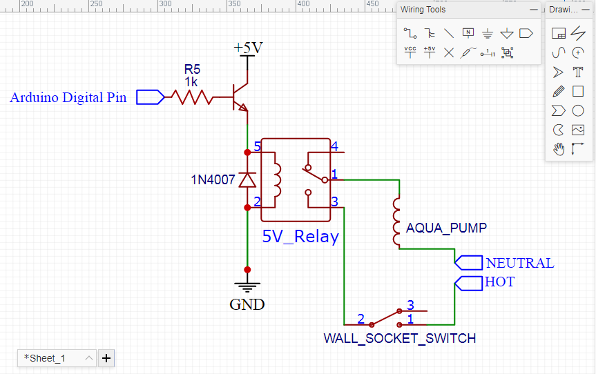
@SteveJG I really would like to thank you for the insight you have provided. I have tried to put things in a drawing to give a better clarity. Just after connecting arduino to my mobile, if I switch on my Wall_Socket_Switch, that's it. It hangs the app when i try to establish serial connection with arduino. AC power connection is still open. No current could possibly flow as the relay is still open
I am yet to try to the radio method you suggested to find the issue
If I turn on the Wall_Socket_Switch and then connect my mobile to arduino and then establish serial communication, its working. But only till a point when relay turns off the pump. It should be because of arcing of relay you have already explained in your first answer. I can understand it. This is second issue and a logical issue (contacts arcing)
I am working on RC values to solve this arcing issue. Any suggestion for Capacitance and Resistance value for 18W/230VAC pump and 400W/230VAC well pump? I am thinking of using 0.33uF/630V Capacitor with 220 ohms/1W Resistor in series
I am expecting that it could fix the weird first issue as well. I am facing similar issue with 16X2 LCD also
That power supply is pretty frightening.Try it with a normally regulated and filtered supply. At least add a graetz bridge and capacitors. A few hundred to 1-2k microfarad electrolite will suffice.