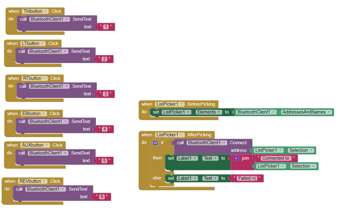
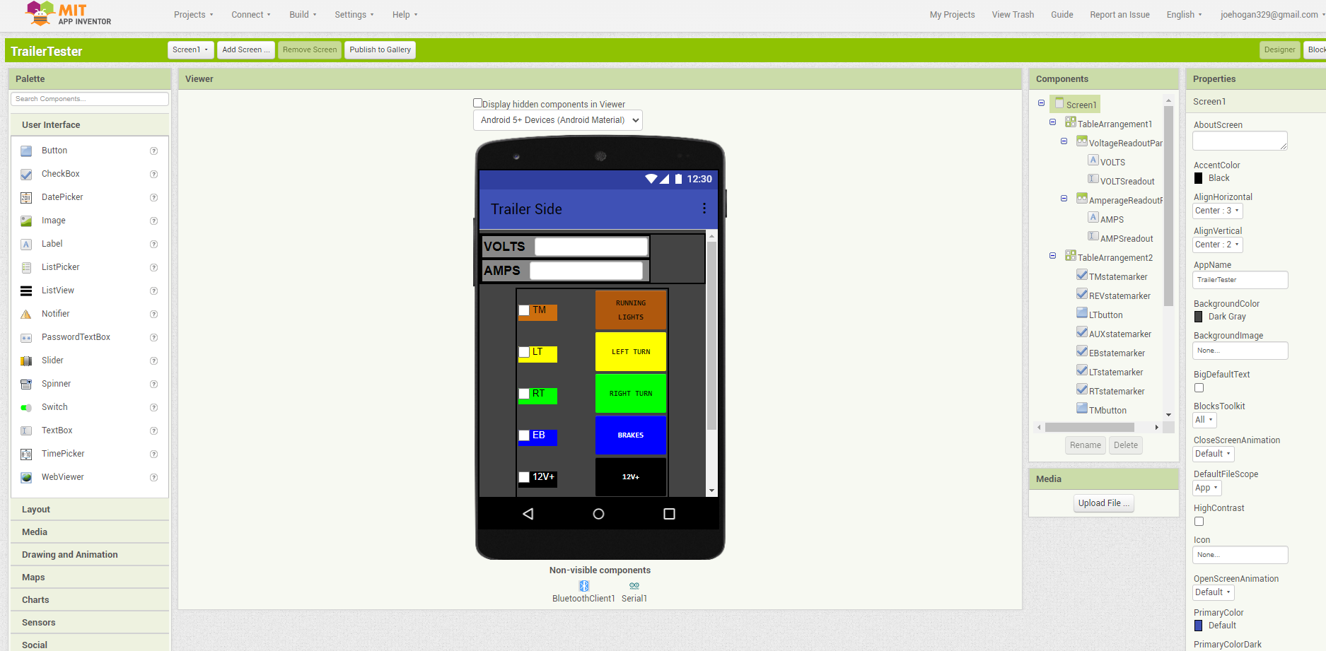
I'm controlling a relay board with an Arduino and trying to make an app to control the Arduino. There's a HC-05 module transmitting the serial communications over blue tooth. My app has buttons with checkboxes next to them. I got the buttons to work the way I want them to. I can click the buttons and the relays toggle on and off. The part I'm having trouble with is... when the relays toggle, their state is written to serial and I'd like the checkboxes next to the buttons to check/uncheck according to the state of the relay pin, just as an indicator so I can tell at glace through the app which relays are currently on or off. I can connect to the Arduino with a Bluetooth Serial Monitor app and see all the pin state data but I don't know how to set it up with the blocks so that it uses this data in the app to toggle the checkboxes. Any help with this would be greatly appreciated! Will provide any other information and details that may be needed.
First show the code from arduino. And the blocks you tried to read the state with.
Ok... Ima do the best I can... Not sure how to make this look neat and tidy so I'll just dump out a copy/past of the arduino sketch with a screenshot of the blocks if that's okay...
Sketch:
#include <SoftwareSerial.h>

SoftwareSerial mySerial(10, 11); // RX, TX

boolean pin2State = false;

boolean pin3State = false;

boolean pin4State = false;

boolean pin5State = false;

boolean pin6State = false;

boolean pin7State = false;

const int analogPin1 = A0; // define analog pins

const int analogPin2 = A1;

const int analogPin3 = A2;

const int analogPin4 = A3;

const int analogPin5 = A4;

const int analogPin6 = A5;

int analogVal1, analogVal2, analogVal3, analogVal4, analogVal5, analogVal6;

int state1 = 0, state2 = 0, state3 = 0, state4 = 0, state5 = 0, state6 = 0;

unsigned long pin3LastToggleTime = 0;

unsigned long pin4LastToggleTime = 0;

unsigned long pin3BlinkStartTime = 0;

unsigned long pin4BlinkStartTime = 0;

const unsigned long TOGGLE_INTERVAL = 100; // Milliseconds

const unsigned long BLINK_INTERVAL = 500;  // Milliseconds

void setup() {

  pinMode(2, OUTPUT);

  pinMode(3, OUTPUT);

  pinMode(4, OUTPUT);

  pinMode(5, OUTPUT);

  pinMode(6, OUTPUT);

  pinMode(7, OUTPUT);

  Serial.begin(9600);

  mySerial.begin(9600);

}

void blinkTurnSignal(int pin, unsigned long startTime) {

  if ((millis() - startTime) % BLINK_INTERVAL < BLINK_INTERVAL / 2) {

    digitalWrite(pin, HIGH);

  } else {

    digitalWrite(pin, LOW);

  }

}

void loop() {


  analogVal1 = analogRead(analogPin1); // read analog values

  analogVal2 = analogRead(analogPin2);

  analogVal3 = analogRead(analogPin3);

  analogVal4 = analogRead(analogPin4);

  analogVal5 = analogRead(analogPin5);

  analogVal6 = analogRead(analogPin6);


  if (mySerial.available()) {

    char command = mySerial.read();

    switch(command) {

      case '1':

        pin2State = !pin2State;

        digitalWrite(2, pin2State);

        mySerial.print("TrlTM state: ");

        mySerial.println(pin2State);

        break;

      case '2':

        if (millis() - pin3LastToggleTime >= TOGGLE_INTERVAL) {

          pin3LastToggleTime = millis();

          pin3State = !pin3State;

          if (pin3State) {

            pin3BlinkStartTime = millis();

          }

          digitalWrite(3, pin3State);

          mySerial.print("TrlLT state: ");

          mySerial.println(pin3State);

        }

        break;

      case '3':

        if (millis() - pin4LastToggleTime >= TOGGLE_INTERVAL) {

          pin4LastToggleTime = millis();

          pin4State = !pin4State;

          if (pin4State) {

            pin4BlinkStartTime = millis();

          }

          digitalWrite(4, pin4State);

          mySerial.print("TrlRT state: ");

          mySerial.println(pin4State);

        }

        break;

      case '4':

        pin5State = !pin5State;

        digitalWrite(5, pin5State);

        mySerial.print("TrlEB state: ");

        mySerial.println(pin5State);

        break;

      case '5':

        pin6State = !pin6State;

        digitalWrite(6, pin6State);

        mySerial.print("TrlAUX state: ");

        mySerial.println(pin6State);

        break;

      case '6':

        pin7State = !pin7State;

        digitalWrite(7, pin7State);

        mySerial.print("TrlREV state: ");

        mySerial.println(pin7State);

        break;

      default:

        break;

    }

  }

if (analogVal1 >= 75 && state1 == 0) { // check if state has changed

    mySerial.println("VehTMON"); // print state to serial

    state1 = 1; // update state

  } else if (analogVal1 < 75 && state1 == 1) {

    mySerial.println("VehTMOFF");

    state1 = 0;

  }

  if (analogVal2 >= 75 && state2 == 0) {

    mySerial.println("VehLTON");

    state2 = 1;

  } else if (analogVal2 < 75 && state2 == 1) {

    mySerial.println("VehLTOFF");

    state2 = 0;

  }

  if (analogVal3 >= 75 && state3 == 0) {

    mySerial.println("VehRTON");

    state3 = 1;

  } else if (analogVal3 < 75 && state3 == 1) {

    mySerial.println("VehRTOFF");

    state3 = 0;

  }

  if (analogVal4 >= 75 && state4 == 0) {

    mySerial.println("VehEBON");

    state4 = 1;

  } else if (analogVal4 < 75 && state4 == 1) {

    mySerial.println("VehEBOFF");

    state4 = 0;

  }

  if (analogVal5 >= 75 && state5 == 0) {

    mySerial.println("VehAUXON");

    state5 = 1;

  } else if (analogVal5 < 75 && state5 == 1) {

    mySerial.println("VehAUXOFF");

    state5 = 0;

  }

  if (analogVal6 >= 75 && state6 == 0) {

    mySerial.println("VehREVON");

    state6 = 1;

  } else if (analogVal6 < 75 && state6 == 1) {

    mySerial.println("VehREVOFF");

    state6 = 0;

  }


  if (pin3State) {

    blinkTurnSignal(3, pin3BlinkStartTime);

  }

  if (pin4State) {

    blinkTurnSignal(4, pin4BlinkStartTime);

  }

delay(100); // add a short delay to debounce analog readings

}
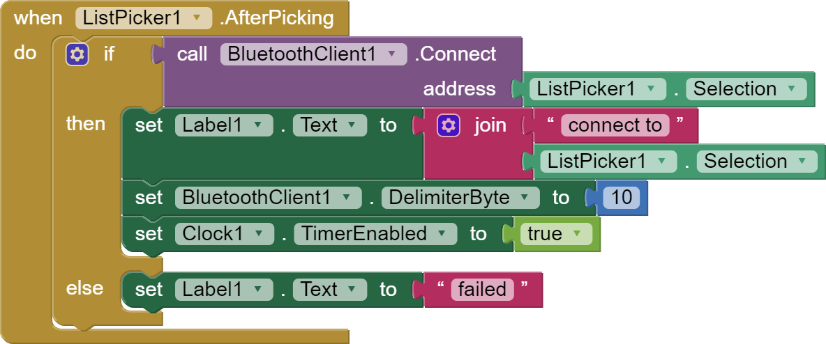
OMG thank you so much! I finally have the serial data showing up in the app! I think I can get the rest worked out from here, thank you again!
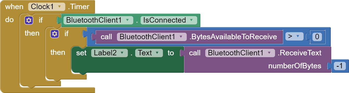
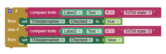
"I think I can get the rest worked out from here"... I spoke too soon... So now I have a label that's displaying the serial data. When I hit the 'running lights' button the label brings up 'TrlTM state: 1' but I can't find the blocks to make it so that when that message is received the 'TM' checkbox fills. I thought it would be an option like "if Label2 text reads: "custom text", then set TMstatemarker to TRUE... or something like that... but that doesn't appear to be in the available blocks
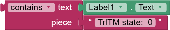
Theoretically, this should work. Unless the message contains some invisible characters. Maybe instead of compare block use a block:
I'll try that and see what happens. I also just noticed this caution symbol. It sounds like
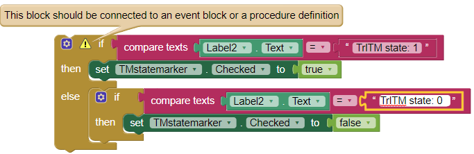
I need to put it inside something else?
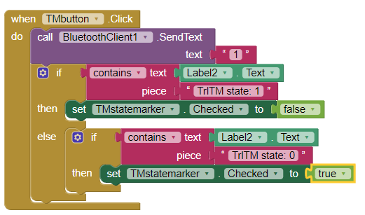
Ok so I tried your way, attached it to the TMbutton block, had to reverse the true/false logic for some reason, but that did it!
Thank you so much!!!
I'd love to get more done on this but I've been toiling away at this project all weekend and haven't even been outside since Friday so I'll pick this back up next weekend to try and get the volt-meter and amp-meter working. I'm super thrilled by how much of it has gotten done in just this weekend. I made another one of these tester boxes a few years ago using RoboRemo as the app interface (that was my first whack at making one of these and controlling it with an android tablet) and that version took me over a hear to get everything together(and didn't have state indicators) so the fact that this has come together this far in a day and a half this time around is just amazing! Would love to pick your brain about how to get those volt and amp values into the app when the time comes if that's something you'd be willing to help me with!
Now I see that you have placed the text detection block from the label in the button. I don't think it will work well. You must place the text detection blocks in the clock under the label.
Yessir that made itself apparent to me really quick lol
This topic was automatically closed 7 days after the last reply. New replies are no longer allowed.