How is the app supposed to know if the resistance is in air versus in gas?
- Just by its behavior over time, or
- by some extra input?
How is the app supposed to know if the resistance is in air versus in gas?
I will add an input of response and recovery time, and they will be the same time. For example, I need to get resistance every 60 seconds, or input time, which I can add in the app itself. I am using this app for my PhD work.
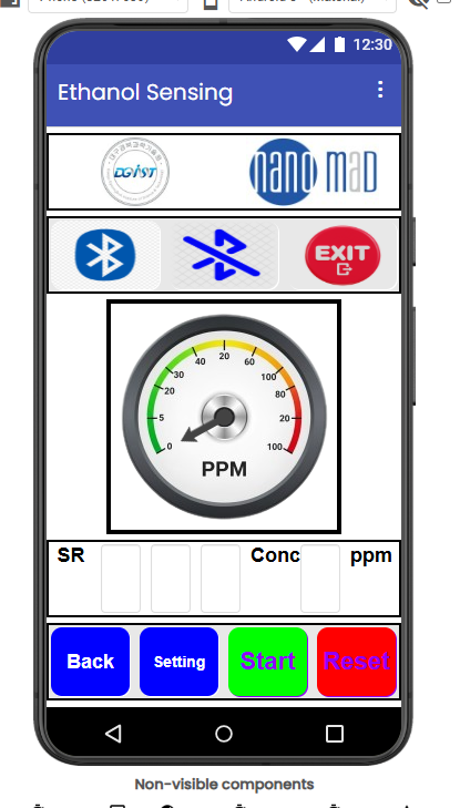
My app will be for gas sensing that can take the data from the ESP32 as voltage and convert it to resistance using a Wheatstone bridge. After that, convert the resistance to a sensor response using R/Rbaseline. What I also have to set is the response and recovery time in the app to calculate the R baseline and R for gas; then it can convert the detected sensor response to ppm using the calibration screen from the slope itself. Also, I need to make three layers for alarming green, yellow, and red by something like a gauge shown on the screen and also send an alarm to the user.
Belalv4.aia (1.9 MB)
Sorry, I don't understand these values.
Are they
Input parameters by text boxes
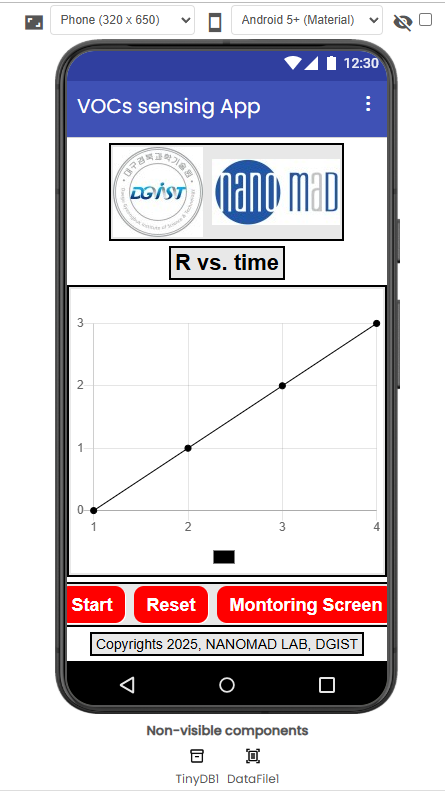
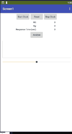
Here's a sample app that calculates response time from the input stream.
(The test run has a negative time, before I switched the before and after readings in the blocks.)
I will await a specific question about a specific piece of code.
I leave it to you to read your own code and any other code you may have dragged into your project. You should understand every block and screen of your project.
Here are some inconsistencies I see in your code:
Also, it is time you renamed all your procedures to describe their functions.
The blocks editor has in the past destroyed procedures that have been left in their default names for too long.
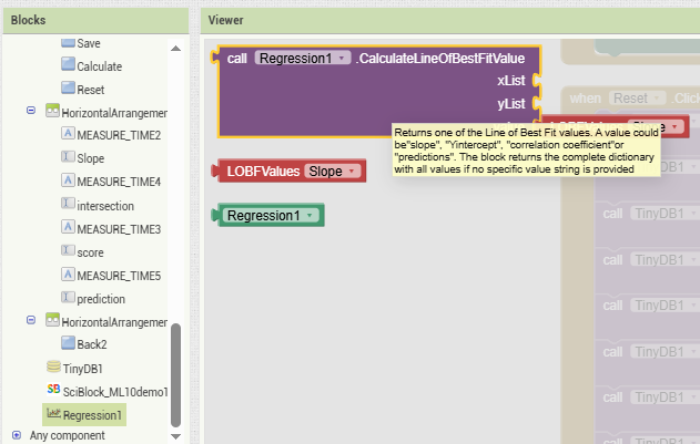
By the way, the AI2 Data Science Designer folder has a component with a block to do linear regression.
Good luck with your extension.
I don't support extensions.
Thank you so much
Actually I will work on my code to link the functions together and also recieving data by Bluetooth and converting Voltage to resistance then to response and concentration in ppm, then degrees to rotate the arrow.
So tomorrow I will send my project to check
Thanks ![]()
![]()
When you have no experience with connecting AI2 to a Bluetooth device, it is helpful to get a Bluetooth terminal app from the Play Store to see the data coming from the device, independent of your AI2 app.
Thanks
How can I utilize the resistance baseline project to read real-time data? It can then compute it and send me the voltage. Also, I want to know if I can get resistance directly from the Arduino.
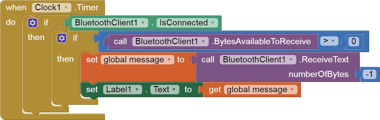
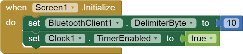
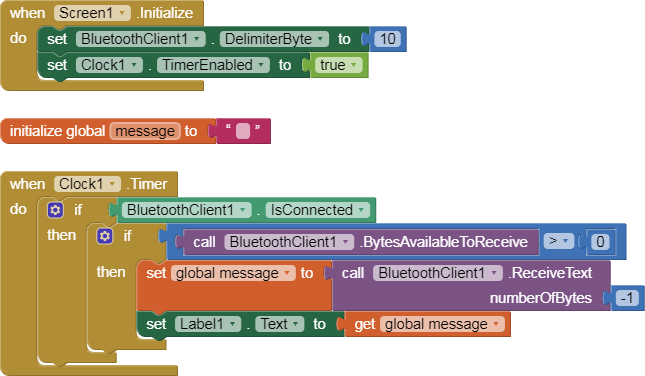
To modify that project for real time data coming from a Bluetooth text stream, merge the Clock Timer with this code:
Here is a simple BlueTooth text receiver sample, for single value per line:

...
This code assumes the resistances are send from the Arduino using the println(resistance) command, which converts the resistance to text and ends it with the mandatory \n character.
Instead of feeding the incoming message to a Label, capture the current Clock1.SystemTime and feed the time and message into the graph and readings list of the aforementioned graph project.
I have no idea how your Arduino setup works.
You would need to post the wiring diagram and the code, and hope for one of our hardware fans to chime in.
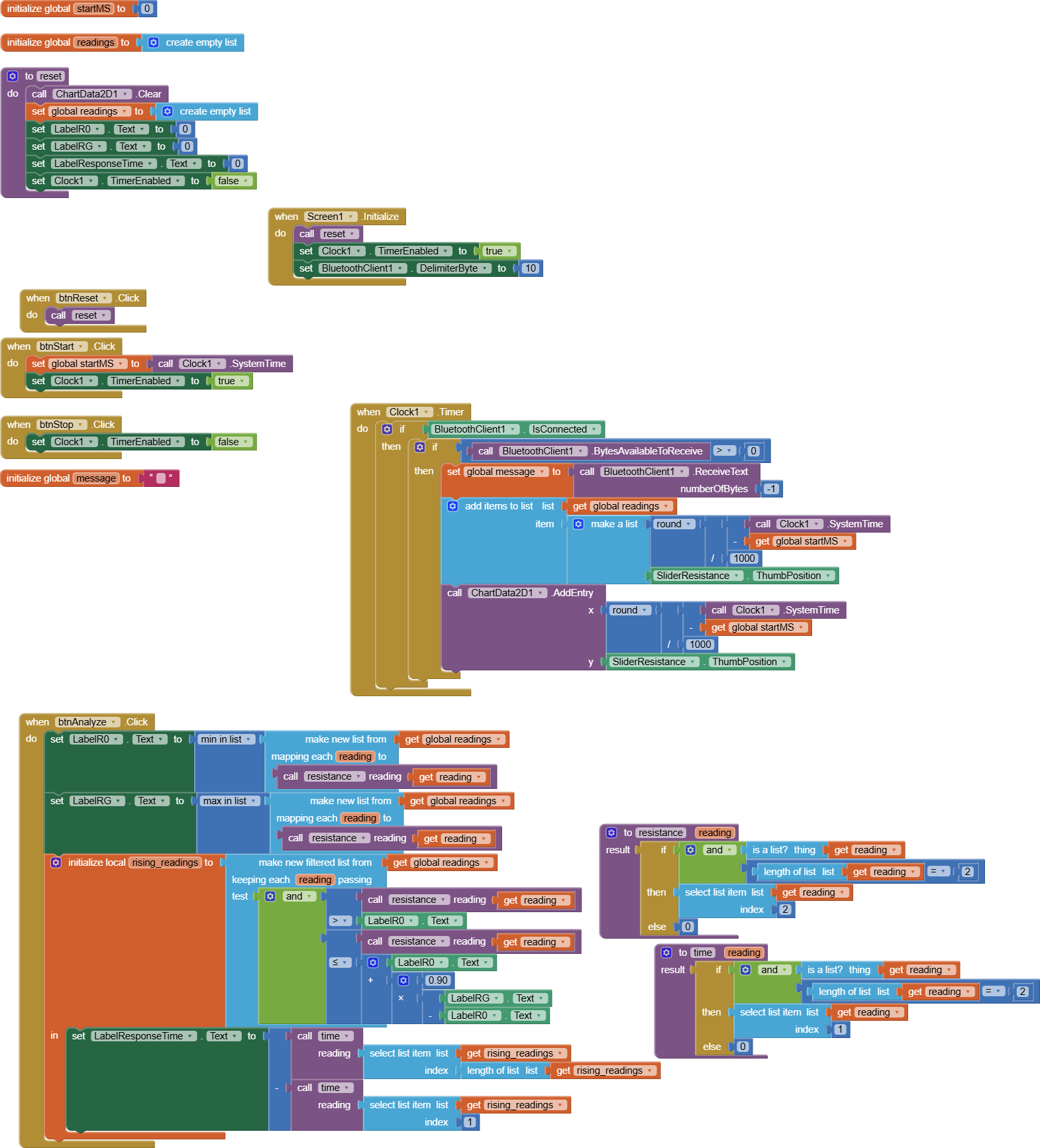
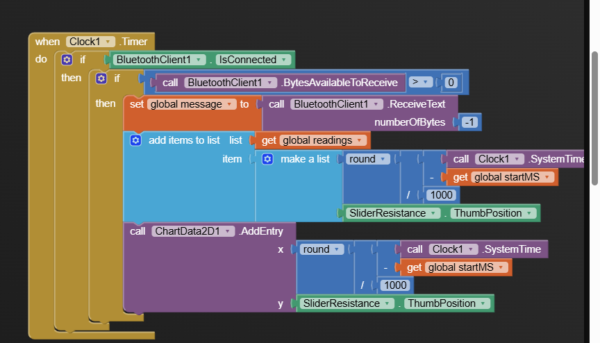
The Clock timer should log the message, not my test slider thumb.
I included the slider in my sample app to simulate input.
Delete the slider component, and use the global message variable value instead to feed the graph and the logging.
Thanks. I also changed the Arduino code with the help of ChatGPT, as I have no experience with it and I am still learning it. I will add the mobile app in the code when I finish checking the Arduino code itself.
Thanks.
#include <Wire.h>
#include <Adafruit_ADS1X15.h>

#define ADS1115_ADDRESS 0x48
#define NUM_SAMPLES 10

const float V_EXCITATION = 3.3;
const float R1 = 10000.0;
const float R2 = 10000.0;
const float R3 = 10000.0;

#define ADS1115_GAIN GAIN_TWO
const float FSR = 2.048;
const float ADC_MAX_COUNT = 32767.0;
const float V_REF_CENTER = V_EXCITATION * (R3 / (R2 + R3));

Adafruit_ADS1115 ads;

unsigned long startTime = 0;  // 🕒 New variable

float readDifferentialVoltage();
float calculateUnknownResistance(float vAIN0);
void printResults(unsigned long elapsedTime, float differentialVoltage, float rUnknown);

void setup() {
  Serial.begin(115200);
  delay(1000);
  Serial.println("\nESP32 + ADS1115 Wheatstone Bridge Measurement");

  if (!ads.begin(ADS1115_ADDRESS)) {
    Serial.println("Failed to initialize ADS1115. Check wiring and address.");
    while (1);
  }

  ads.setGain(ADS1115_GAIN);

  startTime = millis();  // 🕒 Record the time at start

  Serial.println("Time (ms), Differential Voltage (V), R_Unknown (Ohms)");
  Serial.println("----------------------------------------------------");
}

void loop() {
  unsigned long currentTime = millis();
  unsigned long elapsedTime = currentTime - startTime;  // 🕒 Time since start (starts at 0)

  float differentialVoltage = readDifferentialVoltage();
  float vAIN0 = differentialVoltage + V_REF_CENTER;

  if (vAIN0 < 0.0 || vAIN0 > V_EXCITATION) {
    Serial.println("⚠️ Warning: V_AIN0 out of expected range. Check bridge or wiring.");
  }

  float rUnknown = calculateUnknownResistance(vAIN0);
  printResults(elapsedTime, differentialVoltage, rUnknown);

  delay(100); // 10 Hz sampling
}

float readDifferentialVoltage() {
  long sumCounts = 0;
  for (int i = 0; i < NUM_SAMPLES; i++) {
    sumCounts += ads.readADC_Differential_0_1();
    delay(5);
  }
  float avgCounts = sumCounts / (float)NUM_SAMPLES;
  return avgCounts * (FSR / ADC_MAX_COUNT);
}

float calculateUnknownResistance(float vAIN0) {
  if ((V_EXCITATION - vAIN0) > 0.001) {
    return R1 * vAIN0 / (V_EXCITATION - vAIN0);
  } else if (vAIN0 >= V_EXCITATION) {
    return 9999999.0;
  } else {
    return 0.0;
  }
}

void printResults(unsigned long elapsedTime, float differentialVoltage, float rUnknown) {
  Serial.print(elapsedTime);
  Serial.print(", ");
  Serial.print(differentialVoltage, 6);
  Serial.print(", ");
  Serial.println(rUnknown, 2);
}
We have a ChatGPT blooper reel thread where we collect bad generated code from AI.
Don't be gullible.
I see immediately that the new code has only one serial output stream.
You need two streams, one for console output on the Arduino, for human consumption, and one for Bluetooth output, with consistent format and easy to parse markup in sync with the app Bluetooth stream reader code.
How did you tell the chatbot your pinout setup?
Did you show it your wiring diagram?
Or did you let it hallucinate?
Yes, thanks, I will modify it.
Thanks, now the Arduino code is working with me and reading the exact value of resistance, please I have one question more how I can do the automatic analysis by the aia file you sent, I mean not by clicking the analysis button to analyze many cycles of gas sensing to able for real time sensing which can give concentrations in ppm not only resistance. Also I need to save the data of chart on my mobile in CSV file. One more question how I can add two text boxes for min and max for values of y and x axis. Also, I need to add one pointer to check the values in graph for x and y coordinations.
Your Clock Timer should be polling the BlueTooth input stream and adding each incoming value from the Arduino along with the current SystemTime to a two column table (list of lists), the same way my sample code was taking current Slider thumb values.
How many items per message are arriving in the BlueTooth data stream?
You have not shown the new code.
Your last code shows two variables (differential voltage and rUnknown arriving with an elapsed time.
I have no idea how to convert those to ppm.
You're the expert.
There is a list block to take a table (list of lists) and convert it into a CSV text of a table.
The File component can be used to write text to a file.
The Chart or ChartData component might have blocks to retrieve those.
Assigning a value to a Label.Text or Textbox.Text should be no problem for you by now, once you have the value.
If you want to get min and max from lists, check my sample graph for the calls to Min In List and Max In List.
If you want min and max from columns of a table, use the list block that can make a new list out of an old list by selecting a column from each row.
I find it helpful to document a program before coding it, to such detail that you could hand off that document to a coder.
Imagine that I had no clue how your scheme works.
Explain it to me step by step with real numbers and formulas.
You will need to do this for your PhD oral defense, so it will not be wasted effort.
Thanks for advice
Actually the meaning from this work to learn new skills, so I am doing it myself.
I will provide the scheme of my app and the new Arduino code that I did
#include <Wire.h>
#include <Adafruit_ADS1X15.h>
#include "BluetoothSerial.h"
#define ADS1115_ADDRESS 0x48
#define NUM_SAMPLES 10
// --- BRIDGE AND ADC CONSTANTS (UPDATED FOR 30k RESISTORS) ---
const float V_EXCITATION = 3.3;
// Resistor values are now 30000.0 Ohms (30k)
const float R1 = 30000.0;
const float R2 = 30000.0;
const float R3 = 30000.0;
#define ADS1115_GAIN GAIN_TWO
const float FSR = 2.048;
const float ADC_MAX_COUNT = 32767.0;
// V_REF_CENTER is the voltage at AIN0 (the stable reference point: R3 / (R1 + R3))
const float V_REF_CENTER = V_EXCITATION * (R3 / (R1 + R3)); // 3.3 * (30k / 60k) = 1.65 V
// --- GLOBAL OBJECTS ---
Adafruit_ADS1115 ads;
BluetoothSerial SerialBT;
// --- FUNCTION PROTOTYPES (Simplified parameters) ---
float readDifferentialVoltage();
float calculateUnknownResistance(float differentialVoltage);
// Note: We keep the original parameters in the function calls to loop for simplicity,
// but only use the rUnknown value inside the print functions.
void printConsoleResults(float elapsedTimeSeconds, float differentialVoltage, float rUnknown);
void printBluetoothData(float elapsedTimeSeconds, float differentialVoltage, float rUnknown);
unsigned long startTime = 0;
//=============================================================================
void setup() {
    // 1. Initialize Console Serial
    Serial.begin(115200);
    delay(1000);
    Serial.println("\n--- ESP32 + ADS1115 Corrected Bridge Measurement (30k) ---");
    // 2. Initialize Bluetooth Serial
    SerialBT.begin("Belal_GasSensor");
    Serial.println("Bluetooth device 'Belal_GasSensor' started.");
    // 3. Initialize ADS1115
    if (!ads.begin(ADS1115_ADDRESS)) {
        Serial.println("Failed to initialize ADS1115. Check wiring.");
        while (1);
    }
    ads.setGain(ADS1115_GAIN);
    Serial.print("V_REF_CENTER (V(AIN0)): ");
    Serial.println(V_REF_CENTER, 4); // Should print 1.6500 V
    startTime = millis();
    Serial.println("\nConsole Stream (R_Unknown only):");
    Serial.println("R_Unknown (Ohms)"); // Simplified Header
    Serial.println("----------------");
}
//=============================================================================
void loop() {
    unsigned long currentTime = millis();
    unsigned long elapsedTimeMillis = currentTime - startTime;
    // Calculate elapsed time in seconds (still needed for accurate timing in the loop logic)
    float elapsedTimeSeconds = elapsedTimeMillis / 1000.0;
    float differentialVoltage = readDifferentialVoltage();
    float rUnknown = calculateUnknownResistance(differentialVoltage);
    // Output to both streams
    printConsoleResults(elapsedTimeSeconds, differentialVoltage, rUnknown);
    printBluetoothData(elapsedTimeSeconds, differentialVoltage, rUnknown);
    delay(100); // 0.1 second (100 ms) delay between samples
}
//=============================================================================
float readDifferentialVoltage() {
    long sumCounts = 0;
    for (int i = 0; i < NUM_SAMPLES; i++) {
        sumCounts += ads.readADC_Differential_0_1();
        delay(5);
    }
    float avgCounts = sumCounts / (float)NUM_SAMPLES;
    return avgCounts * (FSR / ADC_MAX_COUNT);
}
//=============================================================================
float calculateUnknownResistance(float differentialVoltage) {
    // 1. Find the voltage at the sensor node (AIN1)
    float V_AIN1 = V_REF_CENTER - differentialVoltage;

    if (V_AIN1 <= 0.0) {
        return 9999999.0;
    }

    // 2. Calculate R_UNKNOWN
    float denominator = V_EXCITATION - V_AIN1;

    if (denominator <= 0.0001) {
        return 9999999.0;
    }
    return R2 * V_AIN1 / denominator;
}
//=============================================================================
void printConsoleResults(float elapsedTimeSeconds, float differentialVoltage, float rUnknown) {
    // Console output: R_Unknown only
    Serial.println(rUnknown, 2);
}
//=============================================================================
void printBluetoothData(float elapsedTimeSeconds, float differentialVoltage, float rUnknown) {
    // Bluetooth output: R_Unknown only
    if (SerialBT.hasClient()) {
        SerialBT.println(rUnknown, 2);
    }
}