I installed a wifi socket widget app from playstor which controls arduino using esp8266-01 module by sending a command "IP address: port/command" and it works good but I want to create an app in MIT app inventor to control this project I tried an approach but failed!
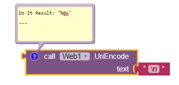
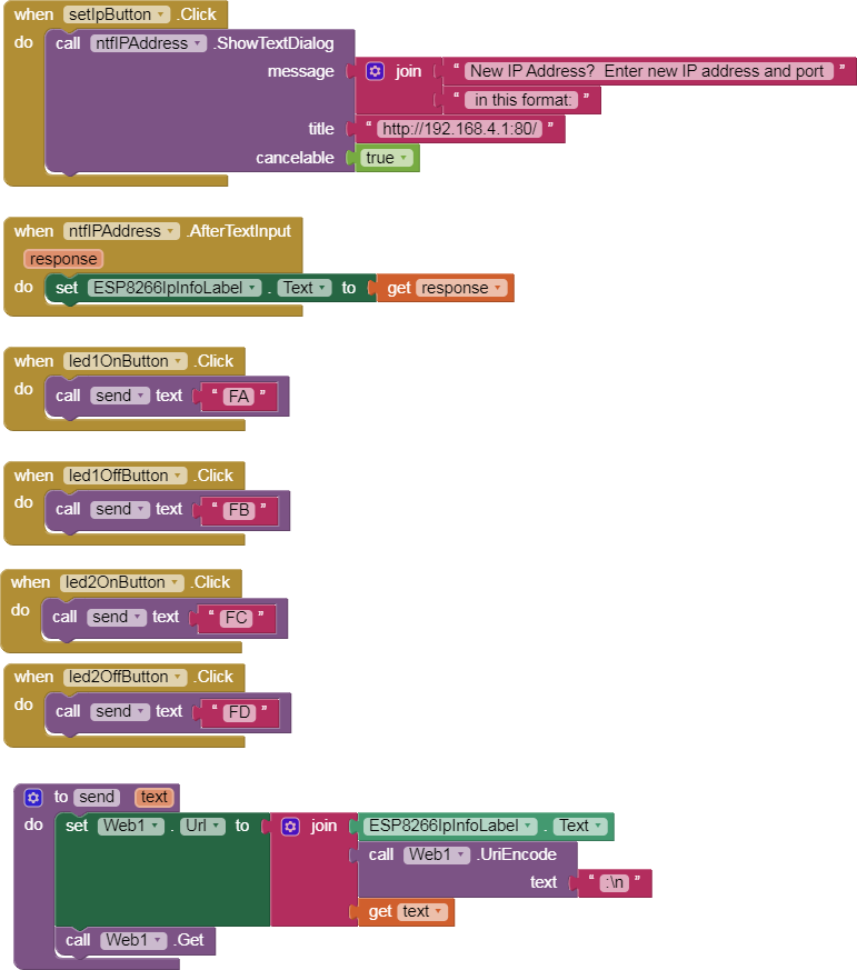
I went through the first post discussions but first of all my problem need to be understood first then anyone can direct me to extensions right. I send commands to other arduino codes they work but the code which I am trying wants \n to receive first then FA to work. Here I am unable to judge how to send " \n "and " FA "........!...?
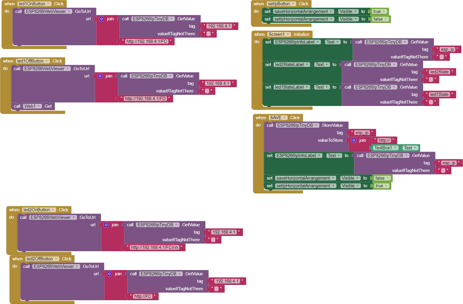
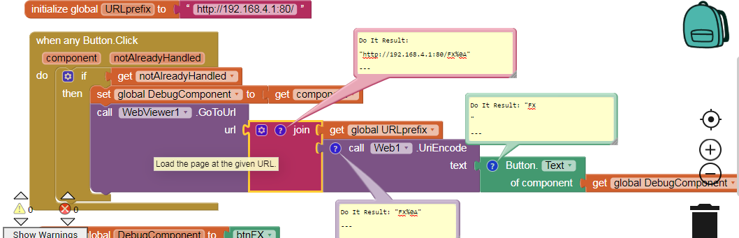
I want to change this blocks code to send some command. My esp ip is 192.168.4.1 and port is 80.
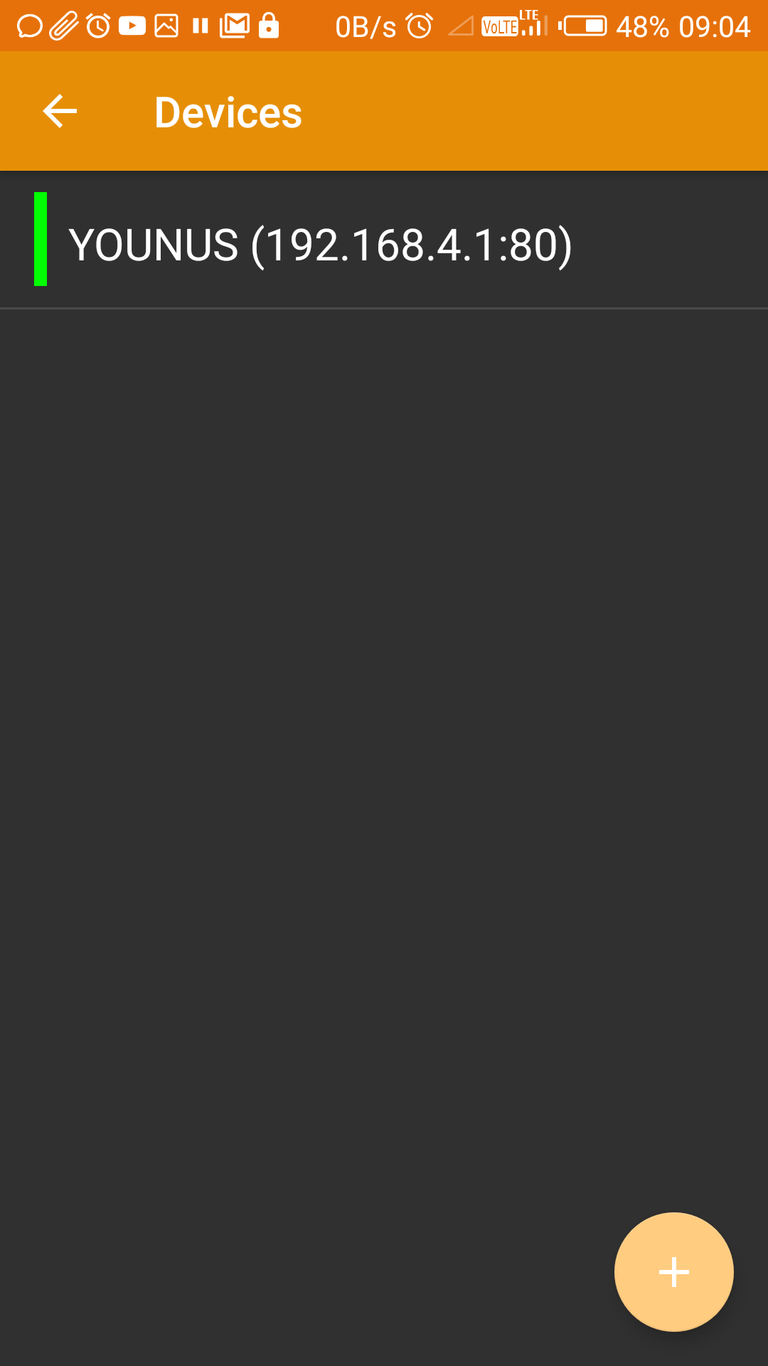
I send command with wifi serial terminal app from play store works good, also when i use Socket Widget App whose screenshot is above, it still works good but when i try send the same command with this app ,wifi just receives commands but not works. I am not ablle to find the exact block that can send the command so that my arduino led works through esp8266 module
Than you for your reply.......
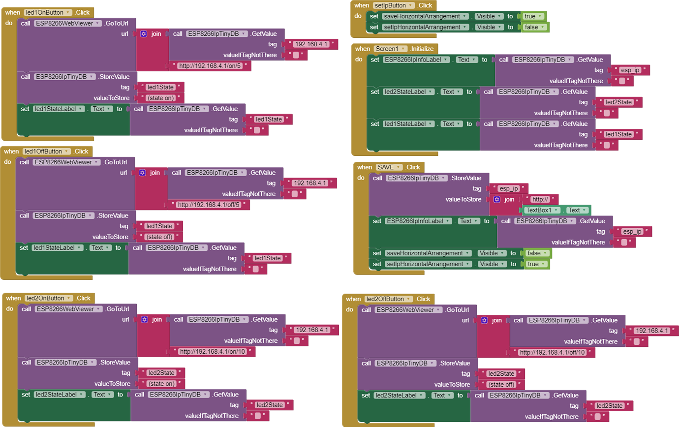
When I click the buttons it opens a web page while as my target is to send commands to esp module offline to make LEDs on arduino on or off. In arduino I check the data on esp and when the proper condition is met LEDs are powered on or off on arduino pins.
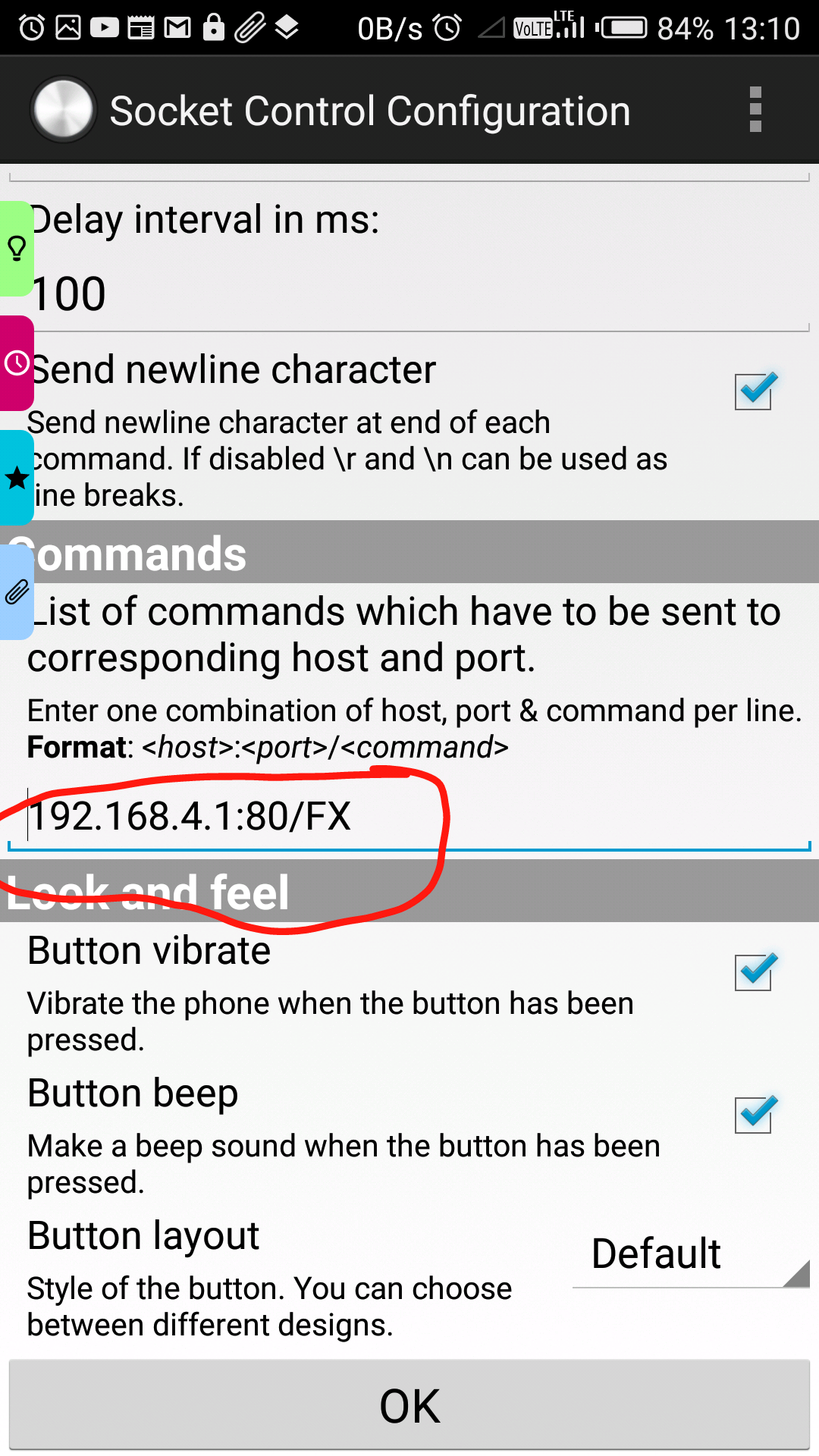
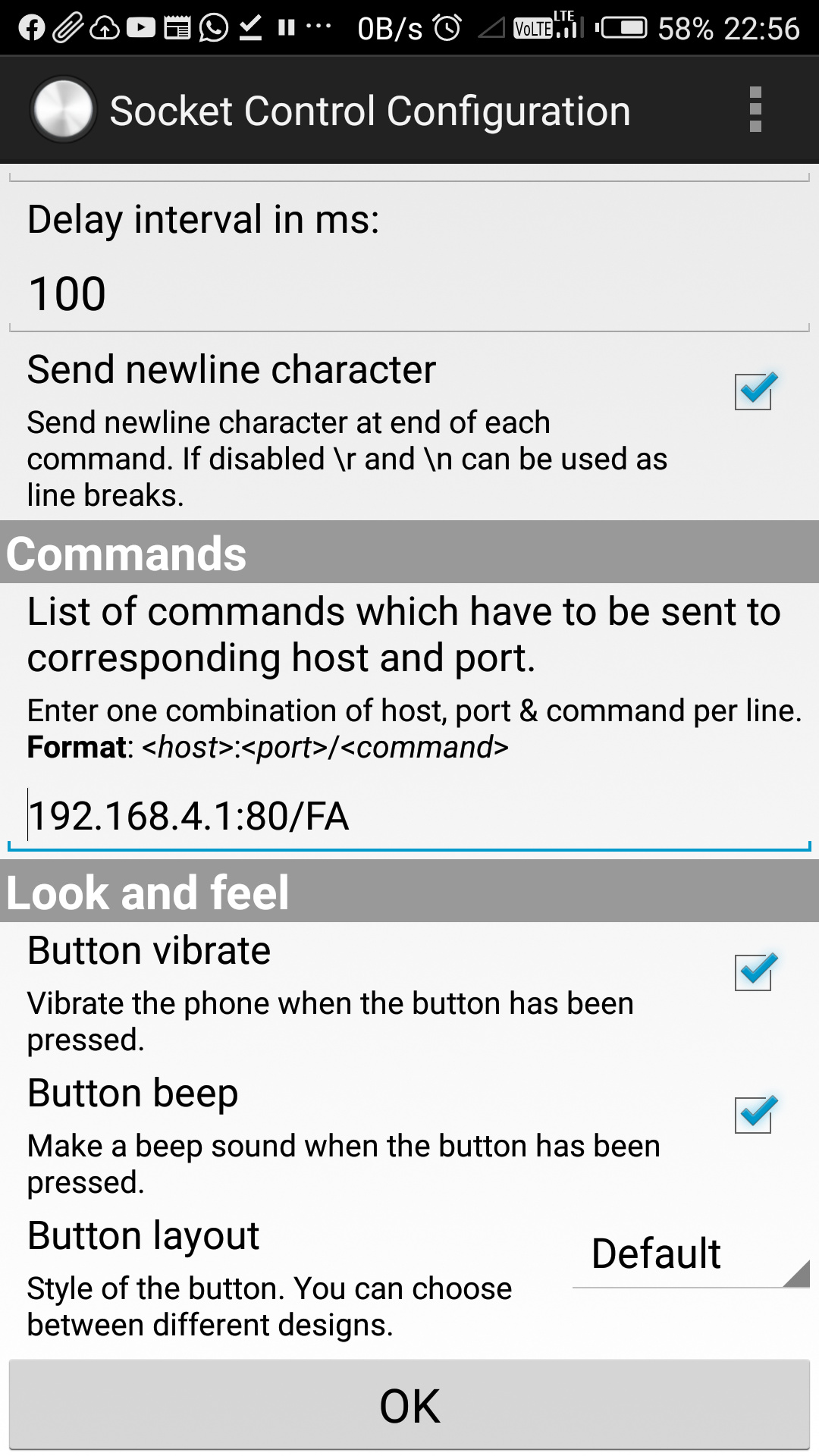
The widget app sends this command to perform the same operation see this widget configuration page:
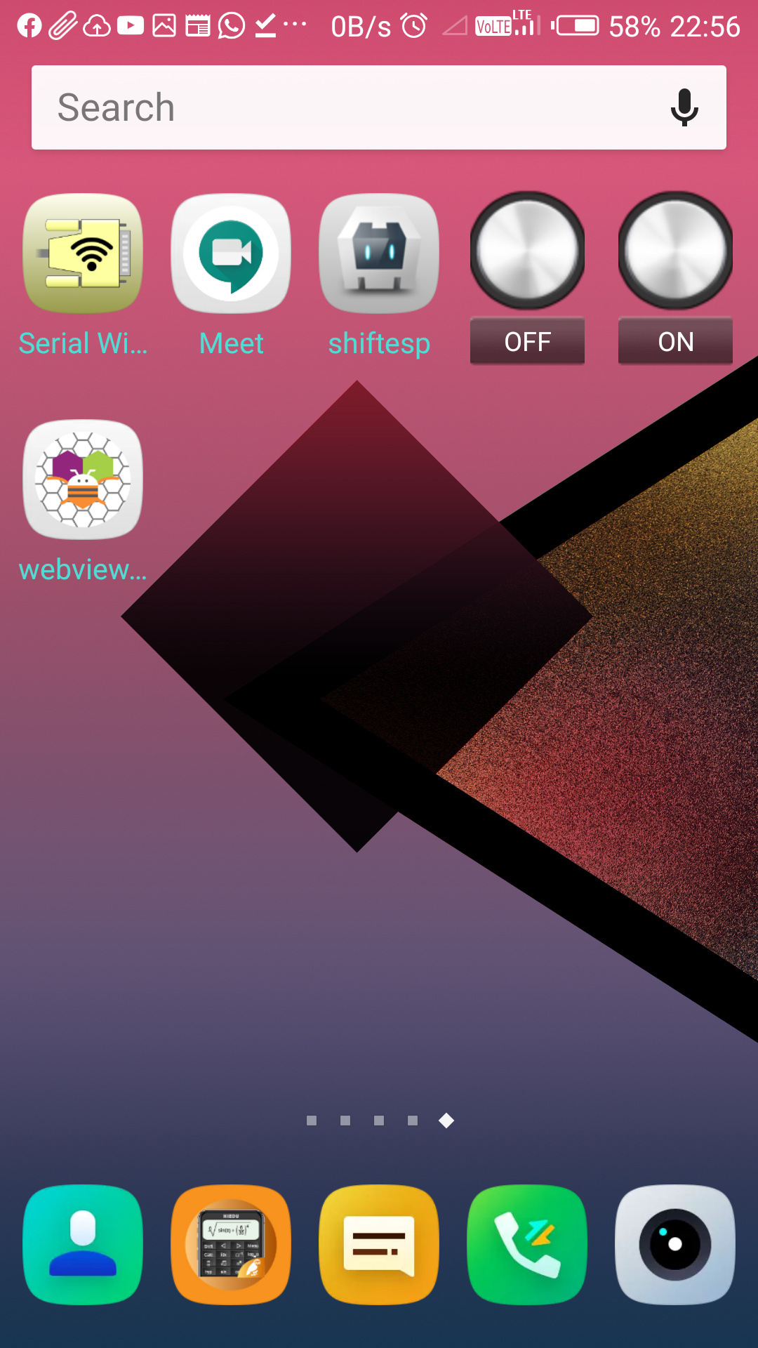
See how its icons look at my phone screen. It needs an additional icon to configure for each command that is why I hate this widget app and I want to make my own app.:
First image : 192.168.4.1:80/FA make arduino led ON if it was off.
Second image : The icons white named as OFF and ON are icons of this widget app.
For OFF button the command is 192.168.4.1:80/FX which makes led OFF.
IMPORTANT NOTE::: Like we send commands to a Bluetooth module in the same way I want to send commands to esp module but here we need an App which first connects to a given IP address and then send a command on button click
Thank you
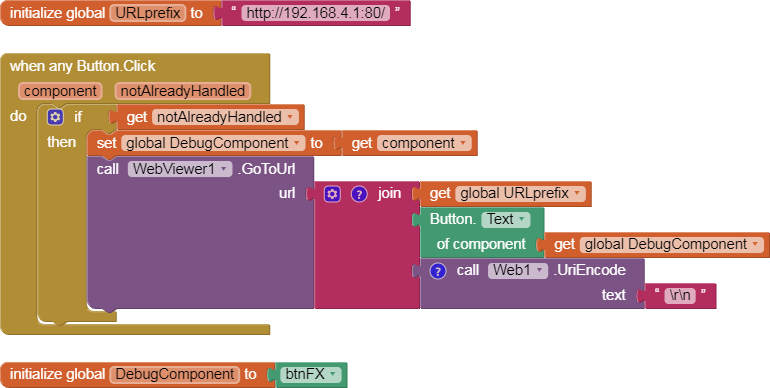
If you don't want to open a web page on the screen, use the Web component instead of the WebViewer.
The URL handling should be the same.
Did the WebViewer solution I posted actually influence the esp8266 ?
IP addresses and clients don't maintain connections like BlueTooth does.
Notice how all the URLs used to talk to the esp8266 fully specify the IP address and port in addition to the current command. It's like sending post cards.
Yes your App sends commands and esp receives them as indicated by blue led on it. And arduino inbuilt led but my output is not changed. It seems that wrong commands are being set.
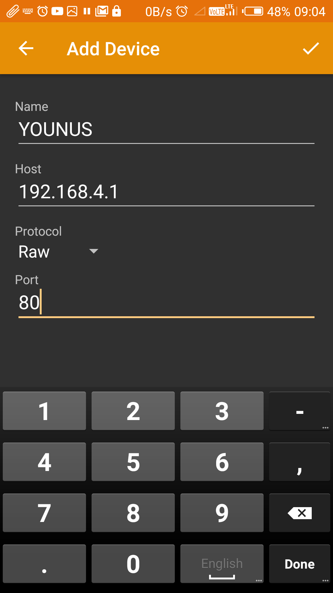
See my experimental results on serial wifi terminal app from play store.
I open it and add a new device then I enter esp NAME or SSID then IP and then PORT
Then I click on it and this screen appears and I write just my command not IP or port I write FA and hit send button , which starts my arduino code perfectly.. See below
But in wifi widget app I need to send Command along with IP and PORT.
So serial app is working..
That is why I believe that esp can work like Bluetooth by just receiving Commands provided ssid etc are set in the app.
But I can not rely on serial App as it is only for experimental purposes and not user friendly , we need to enter command manually.
Can Ai2 send a command to your device that it reads and understands?
Can AI2 support a GUI design to hide that back end stuff behind buttons in a way you like?
If my sample app successfully satisfied item 1 (I am not sure about that), design your own GUI in the Designer, post the .aia file here, and let us show you the back end blocks to send the commands from your GUI.
If my sample app's commands were not understood by your device, we need to have a discussion about the difference between the RAW protocol used by your TERMINAL app and the HTTP protocol used by the Web component.
I'm not ready for such a discussion, especially since I don't see your Arduino code anywhere in this thread.
I have Uploaded aia file see above ESP_2 as previous was not detailed this is my App interface without code blocks see also simple arduino sketch.
thank you.
This is my best try at matching your Arduino codein AI2 Web traffic.
From what I see in your code, you require ':\n' as a prefix for all traffic.
Change that in the AI2 common send procedure if I got that wrong.
Also, your comments in the Arduino code don't match the registers you switch once you get past led 1, so you will have to adjust your codes once you get led 1 working.
