Hello,
I think this maybe since I updated to the new ble extension, I am now unable to connect to it, below is the error.
Service 0000ffe0-0000-1000-8000-00805f9b34fb, characteristic 0000ffe1-0000-1000-8000-00805f9b34fb are not published by the connected device.
Note: You will not see another error reported for 5 seconds.
This aia I put in is a new extension and it connects to my hm10 with no problem. From what you wrote yesterday, after updating the extension, the application was connecting to hm10. See if you have damaged your hm10.
Try this aia:
CI_WITH_TEMP (3).aia (1001.6 KB)
Maybe it is damaged, I seem to be able to write to it from serial monitor and send messages back using BLE Scanner. I will order a new HM10 model to see if that will resolve this.
I'm playing with your app right now with my hm10 and it works fine. I slightly tweaked the design to properly display the arduino data.
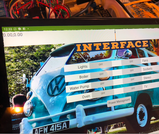
Okay that is good to hear, the app is to control electrical system in a camper van I am currently building as well as provide other data. I hope you like it, I need to tidy it up and tweak it a bit.
Im looking at adding some sort of control for rgb tape as well at some point. I might build a couple of dmx programs for it that can be called up from app inventor via arduino (still on the drawing board)
hello,
New HM10 has arrived. Good and Bad news,
I am connected and have control of relays.
Bad news I have these errors for the temperature
Select list item: Attempt to get item number 2 of a list of length 1: ["["emp. (C): 0.00 "]"]
Note:
Still getting the same issues,
I have tried different pins, updating tablet.....
Still displaying above data and error message
Also sometimes I struggle to connect to hm10 takes a few attempts.
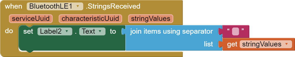
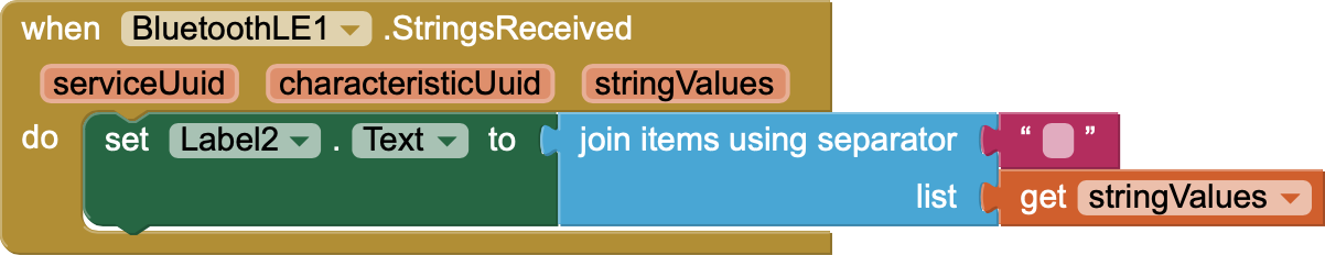
Show what your "when.BluetoothLE1.StringReceived" block looks like. Because with the new aia there should be no square brackets [] in errors.
Drag this block to your project and show the effect on your phone.
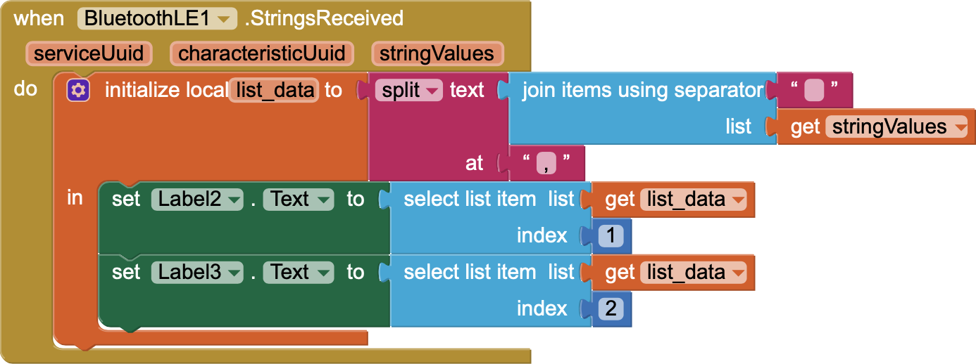
I get the data in the video above using these blocks;
And I get the following messages using the blocks below,
Select list item: Attempt to get item number 2 of a list of length 1: ["emp. (C): 0.00 "]
Note: You will not see another error reported for 5 seconds.
Try it:
/*

Arduino, HM-10, App Inventor 2
Example Project Part 5: 3 leds and 3 switches
By Martyn Currey. www.martyncurrey.com
Turn LEDs on and off from an Android app via a HM-10 or from a physical switches connected to the Arduino
Uses the following pins
D10 - DHT22 data
D9 - AltsoftSerial RX
D8 - AltsoftSerial TX
D7 - LED + resistor
D6 - LED + resistor
D5 - LED + resistor
D4 - Button switch
D3 - Button switch
D2 - Button switch
*/
// AltSoftSerial uses D9 for RX and D8 for TX. While using AltSoftSerial D10 cannot be used for PWM.
// Remember to use a voltage divider on the Arduino TX pin / Bluetooth RX pin
// Download from https://www.pjrc.com/teensy/td_libs_AltSoftSerial.html

// DHT22 uses D10 for data.
// Download from https://botland.com.pl/index.php?controller=attachment&id_attachment=1211

#include <AltSoftSerial.h>
#include <dht.h>;

AltSoftSerial BTserial;

dht DHT22;
#define DHT22PIN 10


// Variables used for incoming data
const byte maxDataLength = 20;
char receivedChars[21] ;
boolean newData = false;

// Constants for hardware
const byte SWITCH_PIN[] = {};
const byte LED_PIN[] = {2,3,4,5,6,7,11,12};

// general variables
boolean LED_State[] = {false,false,false,false};
boolean switch_State[] = {false,false,false,false};
boolean oldswitch_State[] = {false,false,false,false};
unsigned long memory_Time = 0;

void setup()
{
for (byte pin = 0; pin < 8; pin++)
{
// Set the button switch pins for input
pinMode(SWITCH_PIN[pin], INPUT);

     // Set the LED pins for output and make them LOW
     pinMode(LED_PIN[pin], OUTPUT);  digitalWrite(LED_PIN[pin],LOW);
}

// open serial communication for debugging
Serial.begin(9600);
Serial.print("Sketch:   ");   Serial.println(__FILE__);
Serial.print("Uploaded: ");   Serial.println(__DATE__);
Serial.println(" ");

//  open software serial connection to the Bluetooth module.
BTserial.begin(9600);
Serial.println("AltSoftSerial started at 9600");

newData = false;
} // void setup()

void loop()
{
for (byte switchNum = 1; switchNum < 1; switchNum++)
{
checkSwitch(switchNum);
}
recvWithStartEndMarkers(); // check to see if we have received any new commands
if (newData) { processCommand(); } // if we have a new command do something about it

if ((millis() - memory_Time) >= 1000UL){


  // Read the humidity in %:
  float h = DHT22.humidity;
  // Read the temperature as Celsius:
  float t = DHT22.temperature;

  BTserial.print(h);
  BTserial.print(",");
  BTserial.println(t);
  memory_Time = millis();
  }


}

/*

Function checkSwitch()
checks the status of a button switch and turns an LED on or off depending on the switch status
passed:
global:
 switch_State[]
 LED_State[]
 oldswitch_State[]
Returns:
Sets:
 switch_State[]
 LED_State[]
 oldswitch_State[]
*/
void checkSwitch( byte pos)
{
// pos = 1,2,3. Array pos = 0,1,2 so convert by subtracting 1
pos = pos-1;

 // very simple debouce.
 boolean state1 = digitalRead(SWITCH_PIN[pos]); delay(1);
 boolean state2 = digitalRead(SWITCH_PIN[pos]); delay(1);
 boolean state3 = digitalRead(SWITCH_PIN[pos]); delay(1);
 if ((state1 == state2) && (state1==state3))
 {
      switch_State[pos] = state1;
      if ( (switch_State[pos] == HIGH) && (oldswitch_State[pos] == LOW) )
      {
           LED_State[pos] = ! LED_State[pos];  // flip the status.

           // Rather than have a long list of possible commands I create the command as required.
           // Values in the temp command are replaced depending on which button switch has been pressed.
           char TMPcmd[8] = "[L,1,0]";
           TMPcmd[3] = pos+1+48;             // pos+1 should be 1,2, or 3.   convert a numeric value to ascii by adding 48.
           TMPcmd[5] = LED_State[pos]+48;    // LED_State should be 0 or 1
           BTserial.print(TMPcmd);

           digitalWrite(LED_PIN[pos],LED_State[pos]);
           Serial.println(TMPcmd);
      }
      oldswitch_State[pos] = switch_State[pos];
  }
}

/*

Function processCommand
parses data commands contained in receivedChars[]
receivedChars[] has not been checked for errors
passed:
global:
  receivedChars[]
  newData
Returns:
Sets:
  receivedChars[]
  newData
*/
void processCommand()
{
Serial.print("receivedChars = "); Serial.println(receivedChars);

if (receivedChars[0] == 'L')      // do we have a LED command?
{
    // we know the LED command has a fixed length "L10"
    // and the value at pos 1 is the LED and the value at pos 2 is 0 or 1 (on/off).
    // 0 and 1 is the same as LOW and HIGH so we can use 0/1 instead of LOW/HIGH

    byte LEDnum = receivedChars[1] - 48;          // convert ascii to value by subtracting 48
    boolean LEDstatus = receivedChars[2] - 48;

    digitalWrite(LED_PIN[LEDnum-1],LEDstatus);
    LED_State[LEDnum-1] = LEDstatus;
}

receivedChars[0] = '\0';
newData = false;
}

// function recvWithStartEndMarkers by Robin2 of the Arduino forums
// See http://forum.arduino.cc/index.php?topic=288234.0
/*

Function recvWithStartEndMarkers
reads serial data and returns the content between a start marker and an end marker.
passed:
global:
  receivedChars[]
  newData
Returns:
Sets:
  newData
  receivedChars
*/
void recvWithStartEndMarkers()
{
static boolean recvInProgress = false;
static byte ndx = 0;
char startMarker = '[';
char endMarker = ']';
char rc;

 if (BTserial.available() > 0)
 {
      rc = BTserial.read();
      if (recvInProgress == true)
      {
           if (rc != endMarker)
           {
                receivedChars[ndx] = rc;
                ndx++;
                if (ndx > maxDataLength) { ndx = maxDataLength; }
           }
           else
           {
                 receivedChars[ndx] = '\0'; // terminate the string
                 recvInProgress = false;
                 ndx = 0;
                 newData = true;
           }
      }
      else if (rc == startMarker) { recvInProgress = true; }
 }
}
We have a change,
this time the following is being displayed
I have tested the dht22 in a separate sketch and is displaying data in the arduino serial port monitor.
Am I correct in thinking the app isn’t getting the sensor data from BLE module or the app isn’t processing it correctly.
You mean it shows 0.00 instead of value? Did you connect the sensor correctly to the declared pin?
The inscription Temperature and Humidity with the units you want with arduino or do you add it in the label in the application?
App receives 0.00 from arduino and processes it properly. You need to check why the arduino does not read the sensor data in this sketch. Did you use the same library in the test sketch? Place a test sketch on which it worked here.
Yes it isn't showing a value in the lables.
Relay:
GND - COMMON GND (Supplied by Arduino)
IN1 - D2
IN2 - D3
IN3 - D4
IN4 - D5
IN5 - D6
IN6 - D7
IN7 - D11
IN8 - D12
VCC - COMMON 5V (Supplied by Arduino)
GND - Separate Power Supply - GND
JD-VCC - Separate Power Supply - 5V
HM10:
VCC - COMMON 5V (Supplied by Arduino)
GND - COMMON GND (Supplied by Arduino)
TXD - D8
RXD - Voltage Divider (10k & 20k Resistors) - D9
DHT22:
Pos - COMMON 5V (Supplied by Arduino)
Out - D10
Neg - COMMON GND (Supplied by Arduino)
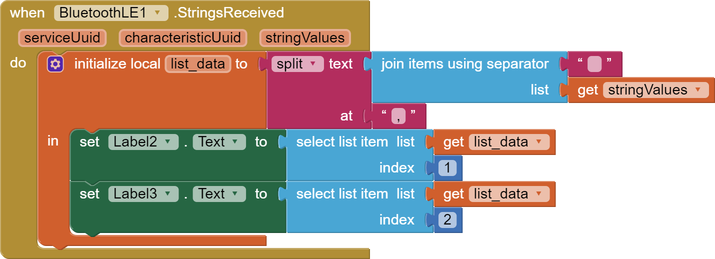
Replace the block in the app with this one:
And upload this to arduino. Humidity will be on the left label, temperature will be on the right.
/*

Arduino, HM-10, App Inventor 2
Example Project Part 5: 3 leds and 3 switches
By Martyn Currey. www.martyncurrey.com
Turn LEDs on and off from an Android app via a HM-10 or from a physical switches connected to the Arduino
Uses the following pins
D10 - DHT22 data
D9 - AltsoftSerial RX
D8 - AltsoftSerial TX
D7 - LED + resistor
D6 - LED + resistor
D5 - LED + resistor
D4 - Button switch
D3 - Button switch
D2 - Button switch
*/
// AltSoftSerial uses D9 for RX and D8 for TX. While using AltSoftSerial D10 cannot be used for PWM.
// Remember to use a voltage divider on the Arduino TX pin / Bluetooth RX pin
// Download from https://www.pjrc.com/teensy/td_libs_AltSoftSerial.html

// DHT22 uses D10 for data.
// Download from https://botland.com.pl/index.php?controller=attachment&id_attachment=1211

#include <AltSoftSerial.h>;
#include <dht.h>;

AltSoftSerial BTserial;

dht DHT22;
#define DHT22PIN 10;


// Variables used for incoming data
const byte maxDataLength = 20;
char receivedChars[21] ;
boolean newData = false;

// Constants for hardware
const byte SWITCH_PIN[] = {};
const byte LED_PIN[] = {2,3,4,5,6,7,11,12};

// general variables
boolean LED_State[] = {false,false,false,false};
boolean switch_State[] = {false,false,false,false};
boolean oldswitch_State[] = {false,false,false,false};
unsigned long memory_Time = 0;

void setup()
{
for (byte pin = 0; pin < 8; pin++)
{
// Set the button switch pins for input
pinMode(SWITCH_PIN[pin], INPUT);

     // Set the LED pins for output and make them LOW
     pinMode(LED_PIN[pin], OUTPUT);  digitalWrite(LED_PIN[pin],LOW);
}

// open serial communication for debugging
Serial.begin(9600);
Serial.print("Sketch:   ");   Serial.println(__FILE__);
Serial.print("Uploaded: ");   Serial.println(__DATE__);
Serial.println(" ");

//  open software serial connection to the Bluetooth module.
BTserial.begin(9600);
Serial.println("AltSoftSerial started at 9600");

newData = false;
} // void setup()

void loop()
{
for (byte switchNum = 1; switchNum < 1; switchNum++)
{
checkSwitch(switchNum);
}
recvWithStartEndMarkers(); // check to see if we have received any new commands
if (newData) { processCommand(); } // if we have a new command do something about it

 // Read the humidity in %:
  float h = DHT22.humidity;
  // Read the temperature as Celsius:
  float t = DHT22.temperature;

if ((millis() - memory_Time) >= 1000UL){


  BTserial.print(h);
  BTserial.print(",");
  BTserial.println(t);
  memory_Time = millis();
  }


}

/*

Function checkSwitch()
checks the status of a button switch and turns an LED on or off depending on the switch status
passed:
global:
 switch_State[]
 LED_State[]
 oldswitch_State[]
Returns:
Sets:
 switch_State[]
 LED_State[]
 oldswitch_State[]
*/
void checkSwitch( byte pos)
{
// pos = 1,2,3. Array pos = 0,1,2 so convert by subtracting 1
pos = pos-1;

 // very simple debouce.
 boolean state1 = digitalRead(SWITCH_PIN[pos]); delay(1);
 boolean state2 = digitalRead(SWITCH_PIN[pos]); delay(1);
 boolean state3 = digitalRead(SWITCH_PIN[pos]); delay(1);
 if ((state1 == state2) && (state1==state3))
 {
      switch_State[pos] = state1;
      if ( (switch_State[pos] == HIGH) && (oldswitch_State[pos] == LOW) )
      {
           LED_State[pos] = ! LED_State[pos];  // flip the status.

           // Rather than have a long list of possible commands I create the command as required.
           // Values in the temp command are replaced depending on which button switch has been pressed.
           char TMPcmd[8] = "[L,1,0]";
           TMPcmd[3] = pos+1+48;             // pos+1 should be 1,2, or 3.   convert a numeric value to ascii by adding 48.
           TMPcmd[5] = LED_State[pos]+48;    // LED_State should be 0 or 1
           BTserial.print(TMPcmd);

           digitalWrite(LED_PIN[pos],LED_State[pos]);
           Serial.println(TMPcmd);
      }
      oldswitch_State[pos] = switch_State[pos];
  }
}

/*

Function processCommand
parses data commands contained in receivedChars[]
receivedChars[] has not been checked for errors
passed:
global:
  receivedChars[]
  newData
Returns:
Sets:
  receivedChars[]
  newData
*/
void processCommand()
{
Serial.print("receivedChars = "); Serial.println(receivedChars);

if (receivedChars[0] == 'L')      // do we have a LED command?
{
    // we know the LED command has a fixed length "L10"
    // and the value at pos 1 is the LED and the value at pos 2 is 0 or 1 (on/off).
    // 0 and 1 is the same as LOW and HIGH so we can use 0/1 instead of LOW/HIGH

    byte LEDnum = receivedChars[1] - 48;          // convert ascii to value by subtracting 48
    boolean LEDstatus = receivedChars[2] - 48;

    digitalWrite(LED_PIN[LEDnum-1],LEDstatus);
    LED_State[LEDnum-1] = LEDstatus;
}

receivedChars[0] = '\0';
newData = false;
}

// function recvWithStartEndMarkers by Robin2 of the Arduino forums
// See http://forum.arduino.cc/index.php?topic=288234.0
/*

Function recvWithStartEndMarkers
reads serial data and returns the content between a start marker and an end marker.
passed:
global:
  receivedChars[]
  newData
Returns:
Sets:
  newData
  receivedChars
*/
void recvWithStartEndMarkers()
{
static boolean recvInProgress = false;
static byte ndx = 0;
char startMarker = '[';
char endMarker = ']';
char rc;

 if (BTserial.available() > 0)
 {
      rc = BTserial.read();
      if (recvInProgress == true)
      {
           if (rc != endMarker)
           {
                receivedChars[ndx] = rc;
                ndx++;
                if (ndx > maxDataLength) { ndx = maxDataLength; }
           }
           else
           {
                 receivedChars[ndx] = '\0'; // terminate the string
                 recvInProgress = false;
                 ndx = 0;
                 newData = true;
           }
      }
      else if (rc == startMarker) { recvInProgress = true; }
 }
}
This is the test sketch I used to ensure the dht22 was functioning and not faulty.
It is a different library to the one you provide me with.
#include <DHT.h>
#include <DHT_U.h>
/* How to use the DHT-22 sensor with Arduino uno
Temperature and humidity sensor
*/
//Libraries
#include <DHT.h>;
//Constants
#define DHTPIN 10 // what pin we're connected to
#define DHTTYPE DHT22 // DHT 22 (AM2302)
DHT dht(DHTPIN, DHTTYPE); //// Initialize DHT sensor for normal 16mhz Arduino
//Variables
int chk;
float hum; //Stores humidity value
float temp; //Stores temperature value
void setup()
{
Serial.begin(9600);
dht.begin();
}
void loop()
{
delay(2000);
//Read data and store it to variables hum and temp
hum = dht.readHumidity();
temp= dht.readTemperature();
//Print temp and humidity values to serial monitor
Serial.print("Humidity: ");
Serial.print(hum);
Serial.print(" %, Temp: ");
Serial.print(temp);
Serial.println(" Celsius");
delay(10000); //Delay 2 sec.
}