I will take a look through this later when I get back and see what I can get working. Thank you
Good evening @Patryk_F, I am having issues importing the libraries from my laptop you have provided.
This is the error I get
[Library] parse library.properties: library.properties not found
any idea on this?
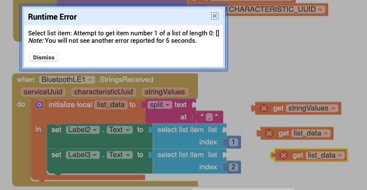
I have added the blocks you have suggested above and am getting this error
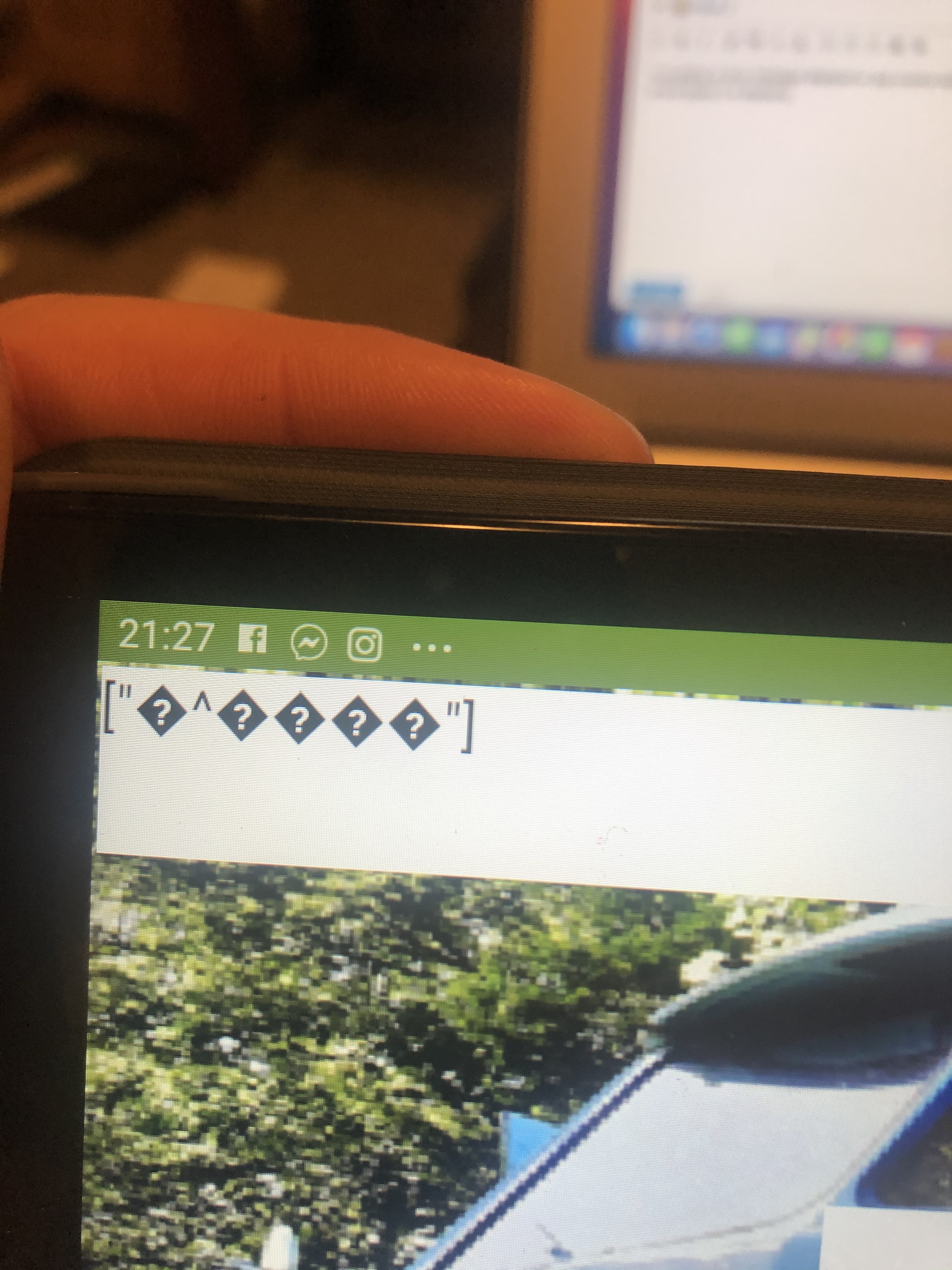
Select list item: Attempt to get item number 2 of a list of length 1: ["["�^����"]"]
Note: You will not see another error reported for 5 seconds.
In the "when.StringReceived" block, remove all blocks and the received data from "stringValues" display in a label. Then show what you got.
After that, did you send some data? Because without the library it probably won't work.
Are any libraries available that are already installed on the IDE web inventor library. The link to the one you have send me gives me the same error each time I try to upload it. I have tried following IDE instructions but it still fails to upload in to library manager. It is probably me doing something stupid.
Block testing is pointless until you upload the modified arduino code. You have to learn to add libraries from a ZIP file. The link I gave is a zip file. You download it, then in the arduino environment you add the zip library pointing to the downloaded file. The link I gave is a zip file. You can look for a different dht22 library, but sometimes the code needs to be modified for a different library.
1 Like
I have finally managed to upload the libraries through the desktop ide.
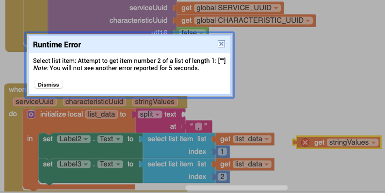
I am getting similar error messages
Upload this code to arduino. I simplified and I only send numbers.
   /*

    Arduino, HM-10, App Inventor 2
    Example Project Part 5: 3 leds and 3 switches
    By Martyn Currey. www.martyncurrey.com
    Turn LEDs on and off from an Android app via a HM-10 or from a physical switches connected to the Arduino
    Uses the following pins
    D10 - DHT22 data
    D9 - AltsoftSerial RX
    D8 - AltsoftSerial TX
    D7 - LED + resistor
    D6 - LED + resistor
    D5 - LED + resistor
    D4 - Button switch
    D3 - Button switch
    D2 - Button switch
    */
    // AltSoftSerial uses D9 for RX and D8 for TX. While using AltSoftSerial D10 cannot be used for PWM.
    // Remember to use a voltage divider on the Arduino TX pin / Bluetooth RX pin
    // Download from https://www.pjrc.com/teensy/td_libs_AltSoftSerial.html

    // DHT22 uses D10 for data.
    // Download from https://botland.com.pl/index.php?controller=attachment&id_attachment=1211

    #include <AltSoftSerial.h>
    #include <dht.h>;

    AltSoftSerial BTserial;

    dht DHT22;
    #define DHT22PIN 10


    // Variables used for incoming data
    const byte maxDataLength = 20;
    char receivedChars[21] ;
    boolean newData = false;

    // Constants for hardware
    const byte SWITCH_PIN[] = {};
    const byte LED_PIN[] = {2,3,4,5,6,7,11,12};

    // general variables
    boolean LED_State[] = {false,false,false,false};
    boolean switch_State[] = {false,false,false,false};
    boolean oldswitch_State[] = {false,false,false,false};
    unsigned long memory_Time = 0;

    void setup()
    {
    for (byte pin = 0; pin < 8; pin++)
    {
    // Set the button switch pins for input
    pinMode(SWITCH_PIN[pin], INPUT);

         // Set the LED pins for output and make them LOW
         pinMode(LED_PIN[pin], OUTPUT);  digitalWrite(LED_PIN[pin],LOW);
    }

    // open serial communication for debugging
    Serial.begin(9600);
    Serial.print("Sketch:   ");   Serial.println(__FILE__);
    Serial.print("Uploaded: ");   Serial.println(__DATE__);
    Serial.println(" ");

    //  open software serial connection to the Bluetooth module.
    BTserial.begin(9600);
    Serial.println("AltSoftSerial started at 9600");

    newData = false;
    } // void setup()

    void loop()
    {
    for (byte switchNum = 1; switchNum < 1; switchNum++)
    {
    checkSwitch(switchNum);
    }
    recvWithStartEndMarkers(); // check to see if we have received any new commands
    if (newData) { processCommand(); } // if we have a new command do something about it

    if ((millis() - memory_Time) >= 1000UL){

    //Read data and store it to variables hum and temp


      BTserial.print((float)DHT22.humidity, 2);
      BTserial.print(",");
      BTserial.println((float)DHT22.temperature, 2);
      memory_Time = millis();
      }


    }

    /*

    Function checkSwitch()
    checks the status of a button switch and turns an LED on or off depending on the switch status
    passed:
    global:
     switch_State[]
     LED_State[]
     oldswitch_State[]
    Returns:
    Sets:
     switch_State[]
     LED_State[]
     oldswitch_State[]
    */
    void checkSwitch( byte pos)
    {
    // pos = 1,2,3. Array pos = 0,1,2 so convert by subtracting 1
    pos = pos-1;

     // very simple debouce.
     boolean state1 = digitalRead(SWITCH_PIN[pos]); delay(1);
     boolean state2 = digitalRead(SWITCH_PIN[pos]); delay(1);
     boolean state3 = digitalRead(SWITCH_PIN[pos]); delay(1);
     if ((state1 == state2) && (state1==state3))
     {
          switch_State[pos] = state1;
          if ( (switch_State[pos] == HIGH) && (oldswitch_State[pos] == LOW) )
          {
               LED_State[pos] = ! LED_State[pos];  // flip the status.

               // Rather than have a long list of possible commands I create the command as required.
               // Values in the temp command are replaced depending on which button switch has been pressed.
               char TMPcmd[8] = "[L,1,0]";
               TMPcmd[3] = pos+1+48;             // pos+1 should be 1,2, or 3.   convert a numeric value to ascii by adding 48.
               TMPcmd[5] = LED_State[pos]+48;    // LED_State should be 0 or 1
               BTserial.print(TMPcmd);

               digitalWrite(LED_PIN[pos],LED_State[pos]);
               Serial.println(TMPcmd);
          }
          oldswitch_State[pos] = switch_State[pos];
      }
    }

    /*

    Function processCommand
    parses data commands contained in receivedChars[]
    receivedChars[] has not been checked for errors
    passed:
    global:
      receivedChars[]
      newData
    Returns:
    Sets:
      receivedChars[]
      newData
    */
    void processCommand()
    {
    Serial.print("receivedChars = "); Serial.println(receivedChars);

    if (receivedChars[0] == 'L')      // do we have a LED command?
    {
        // we know the LED command has a fixed length "L10"
        // and the value at pos 1 is the LED and the value at pos 2 is 0 or 1 (on/off).
        // 0 and 1 is the same as LOW and HIGH so we can use 0/1 instead of LOW/HIGH

        byte LEDnum = receivedChars[1] - 48;          // convert ascii to value by subtracting 48
        boolean LEDstatus = receivedChars[2] - 48;

        digitalWrite(LED_PIN[LEDnum-1],LEDstatus);
        LED_State[LEDnum-1] = LEDstatus;
    }

    receivedChars[0] = '\0';
    newData = false;
    }

    // function recvWithStartEndMarkers by Robin2 of the Arduino forums
    // See http://forum.arduino.cc/index.php?topic=288234.0
    /*

    Function recvWithStartEndMarkers
    reads serial data and returns the content between a start marker and an end marker.
    passed:
    global:
      receivedChars[]
      newData
    Returns:
    Sets:
      newData
      receivedChars
    */
    void recvWithStartEndMarkers()
    {
    static boolean recvInProgress = false;
    static byte ndx = 0;
    char startMarker = '[';
    char endMarker = ']';
    char rc;

     if (BTserial.available() > 0)
     {
          rc = BTserial.read();
          if (recvInProgress == true)
          {
               if (rc != endMarker)
               {
                    receivedChars[ndx] = rc;
                    ndx++;
                    if (ndx > maxDataLength) { ndx = maxDataLength; }
               }
               else
               {
                     receivedChars[ndx] = '\0'; // terminate the string
                     recvInProgress = false;
                     ndx = 0;
                     newData = true;
               }
          }
          else if (rc == startMarker) { recvInProgress = true; }
     }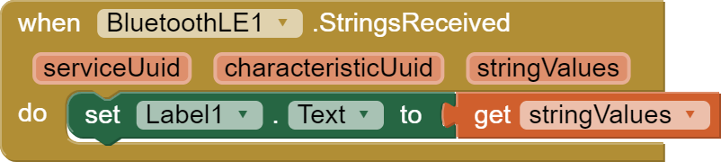
}I am getting no error messages displayed on app inventor itself but on the app where the data should appear It is displaying the following
Have you uploaded a new code to arduino?
Yes checked twice
Is relay control working now?
yep full control of all 8 relays,
this is the file I'm currently using, cleaned up stuff I was not using
CI_WITH_TEMP.aia (971.8 KB)
You are using the old version of the BLE extension. Use the latest version from August 2020.
I ran my hm10 to test. I'll let you know when I find a solution.
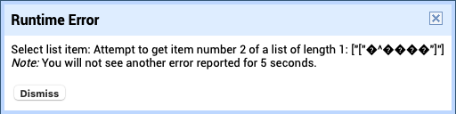
Good spot, still getting same errors
Select list item: Attempt to get item number 2 of a list of length 1: ["["�^����"]"]
Note: You will not see another error reported for 5 seconds.
okay thank you
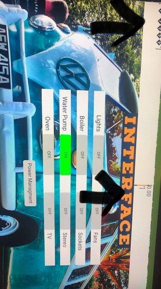
What is this data you showed with the arrow? This is label3.
yes label 2 & label 3
2 to the left, 3 to the right
There was a block error. I fixed it. Here is the aia file. I also updated the blocks above.
CI_WITH_TEMP (1).aia (1001.4 KB)
You can upload the first version of the arduino code back.