Error 507: Unable to connect with HC-05

I am having trouble connecting my cell phone to the HC-05 with Arduino UNO through the created application. My cell phone is a Moto G85 and the HC-05 model is zs-040. The programming created for the HC-05 is working. I tested it with Serial Bluetooth Terminal, and I can connect, send data, and receive data. But with the app, I can't connect. I got the list of Bluetooth devices, but when I click on the HC-05, error 507 occurs. If you can help me, I would appreciate it. Here is the aia file and a photo of the programming.


ESPEC (1).aia (202.1 KB)

Dear @Juan_Barbosa,
I've just given a quick look to your code, but there are several things to think about:
The HC05 is a classic BT interface, therefore the BLE that you've loaded into your app shall be avoided (discarded).
In the screen1.initialize block (missing in your code) you shall ask for the relevant permissions, before you can use the BT. In detail you shall enable, at Android level, the BT and the Geolocalization.
Please search the forum for the tags "BT" and "permissions": you'll find a lot of topics about it and a lot of examples as well.
Another hint is: since you send and receive texts, you would better use the -1 method, as depicted here below:
image

To allow this method you have to set as terminator the 0x0A (or decimal 10) character in your app and your Arduino code shall terminate its last sending with a Linefeed character, that is: you shall use the "BTserial".println(); instruction (please note that "BTSerial" shall be the name that you have given to your BT serial comm's in your UNO code). For the sake of clarity you can have a look to the FAQ (thanks to @ABG ) about BT matters.

Moreover you can find plenty of examples also in other PU's web sites, like those of @ChrisWard (professorrcad.co.uk) , @TIMAI2 (ai2.metricrat.co.uk), @Juan_Antonio (kio4.com).

Last, but not least, when you want to transmit, you don't need to check if incoming characters are available, so you need to remove that "if" block (as per above drawing).

Best wishes. :hugs:

PS it's a good practice, when one needs help on BT comm's, to annex both the app and the Arduino code. :smirk:

3 Likes

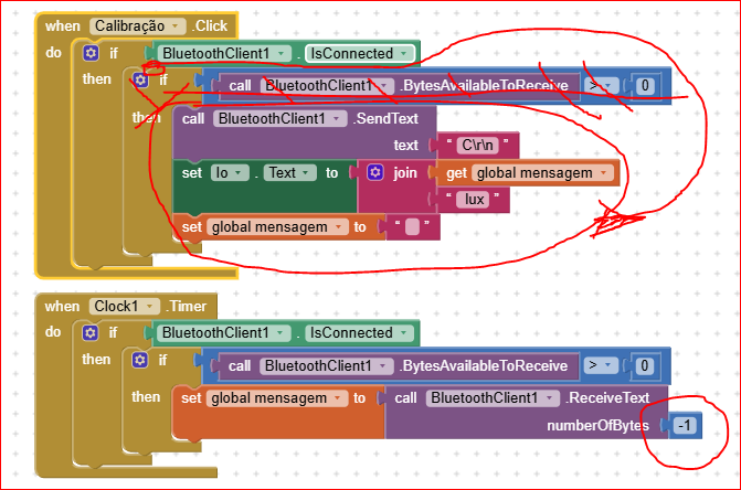
Thank you very much, uskiara. I made the changes here and it helped me a lot. I set the permissions, changed the byte numbers, and removed the BLE. But even so, I couldn't connect through the app, and it was only possible to connect through the terminal. I ran a test with a JDY-31-SPP and, amazingly, it worked and sent the information satisfactorily (I even checked it on the serial monitor and saw it working). So, I don't know what's going on. The HC-05 connects through the terminal but not through the app, but the JDY-31-SPP connects to the app.

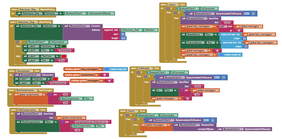
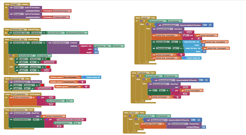
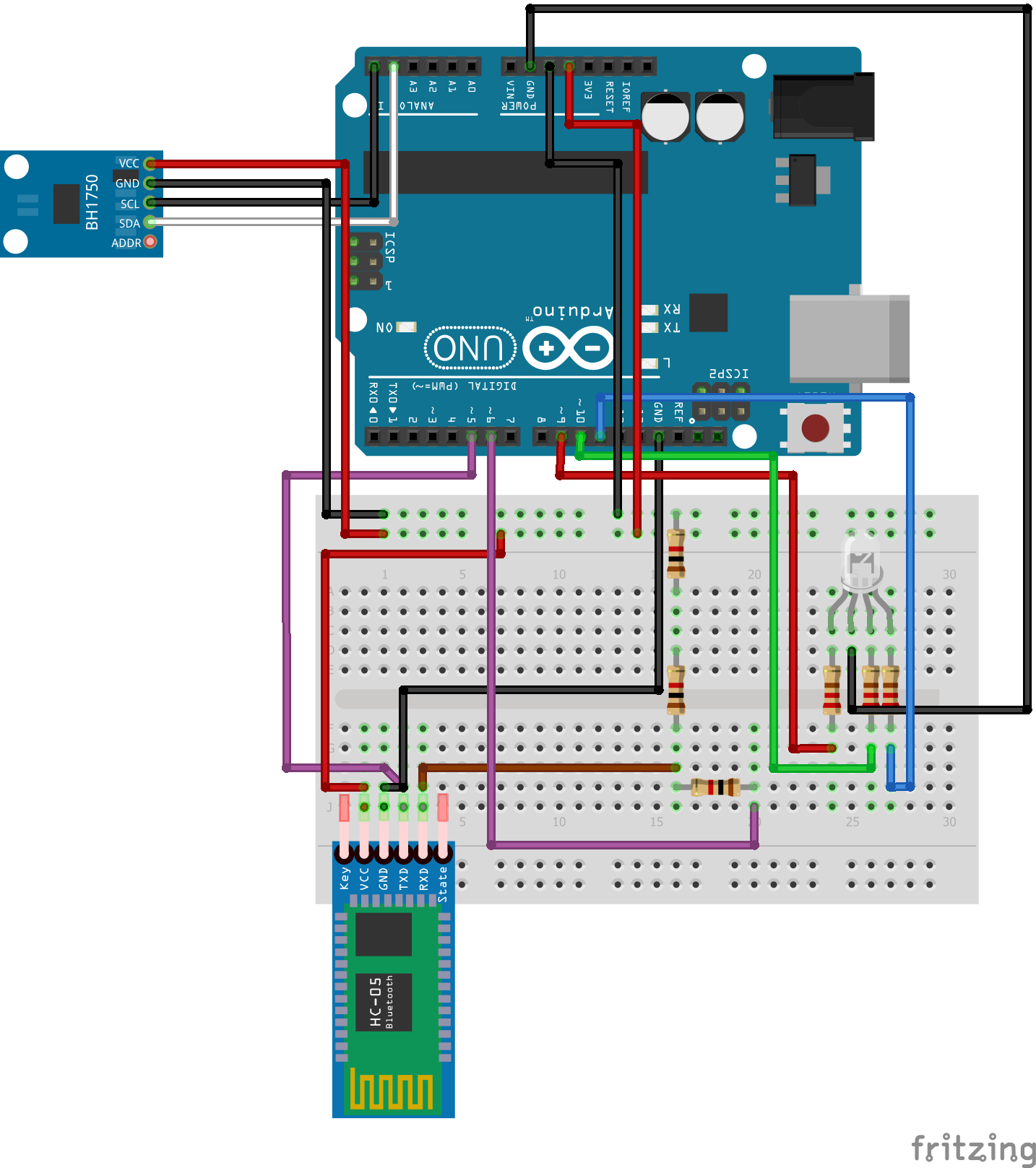
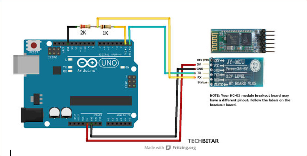
Sorry for not sending the data, I'll send the change in MIT APP INVENTOR, Arduino programming, and the circuit as well.

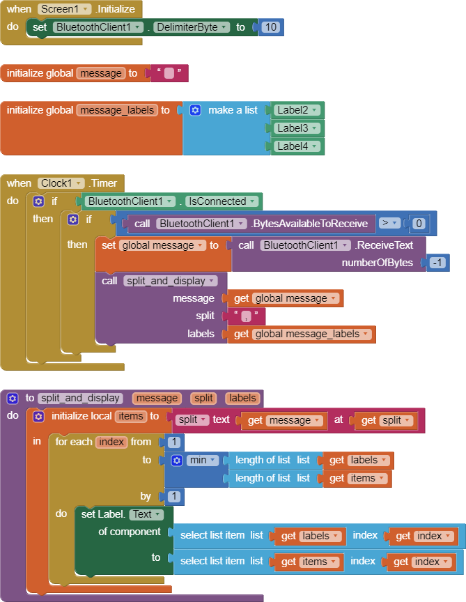
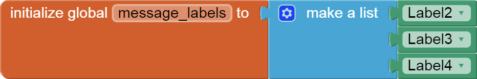
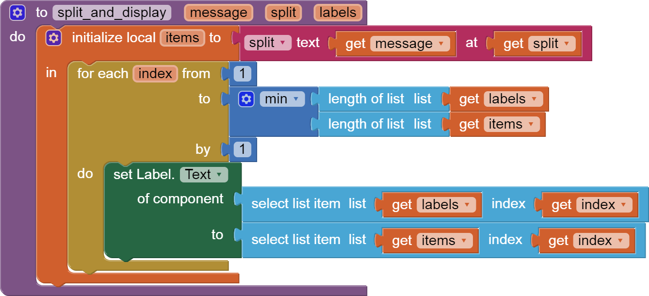
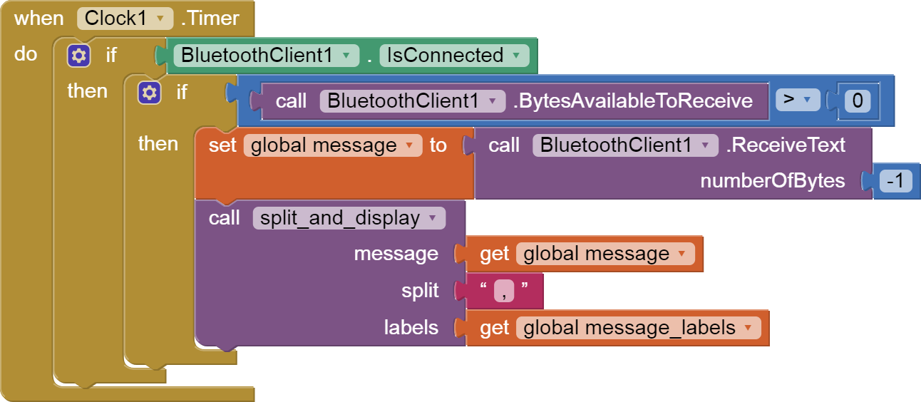
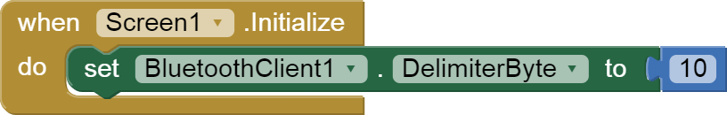
The change in MIT App Inventor is last

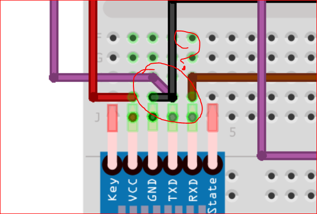
(I made a workaround for the HC-05's RXD because I didn't have a 2K Ohm resistor, using two 1K Ohm resistors instead, if it doesn't matter).


  #include <BH1750.h>
  #include <Wire.h>
  #include <SoftwareSerial.h>

  BH1750 lightMeter(0x23);
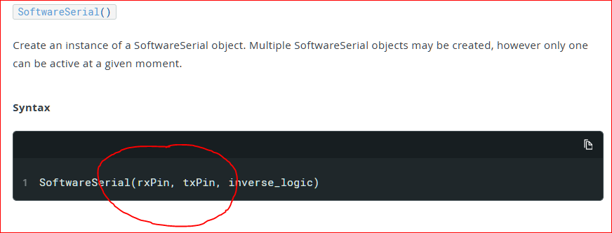
  SoftwareSerial BT(5, 6); // CONNECT BT RX PIN TO ARDUINO 6 PIN | CONNECT BT TX PIN TO ARDUINO 5 PIN
  int pinoR = 9;  // LED vermelho
  int pinoG = 10; // LED verde
  int pinoB = 11; // LED azul
  float Io = 0;   // Referência (branco)
  byte R = 0, G = 0, B = 0;

  String mensagem = ""; // Mensagem recebida

  // Função para converter comprimento de onda em RGB
  void wavelengthToRGB(float wavelength, byte &R, byte &G, byte &B) {
    float red, green, blue;

    if (wavelength >= 380 && wavelength < 440) { // VIOLETA
      red   = -(wavelength - 440) / (440 - 380);
      green = 0.0;
      blue  = 1.0;
    } else if (wavelength >= 440 && wavelength < 485) { // AZUL
      red   = 0.0;
      green = (wavelength - 440) / (485 - 440);
      blue  = 1.0;
    } else if (wavelength >= 485 && wavelength < 500) { // CIANO
      red   = 0.0;
      green = 1.0;
      blue  = -(wavelength - 500) / (500 - 485);
    } else if (wavelength >= 500 && wavelength < 565) { // VERDE
      red   = (wavelength - 500) / (565 - 500);
      green = 1.0;
      blue  = 0.0;
    } else if (wavelength >= 565 && wavelength < 590) { // AMARELO
      red   = 1.0;
      green = -(wavelength - 590) / (590 - 565);
      blue  = 0.0;
    } else if (wavelength >= 590 && wavelength <= 625 ) { // LARANJA
      red   = 1.0;
      green = 1.0 - (wavelength - 590) / (625 - 590); // Verde decresce
      blue  = 0.0;
    } else if (wavelength >= 625 && wavelength <= 780) { // VERMELHO
      red   = 1.0;
      green = -(wavelength - 780) / (780 - 625);
      blue  = 0.0;
    } else {
      red = green = blue = 0.0;
    }
    
    R = (byte) round(red * 255);
    G = (byte) round(green * 255);
    B = (byte) round(blue * 255);
    Serial.print("R: "); Serial.print(R);
    Serial.print(" G: "); Serial.print(G);
    Serial.print(" B: "); Serial.println(B);
  }

  void ligarled() {
    analogWrite(pinoR, R);
    analogWrite(pinoG, G);
    analogWrite(pinoB, B);
  }

  void desligarled() {
    analogWrite(pinoR, 0);
    analogWrite(pinoG, 0);
    analogWrite(pinoB, 0);
  }

  void setup() {
    Serial.begin(9600);
    BT.begin(9600);
    Wire.begin();
    
    pinMode(pinoR, OUTPUT);
    pinMode(pinoG, OUTPUT);
    pinMode(pinoB, OUTPUT);

    if (!lightMeter.begin()) {
      Serial.println("Erro: BH1750 nao encontrado!");
      while (1); // para execução
    }
    Serial.println("BH1750 iniciado com sucesso.");
  }

  void loop() {
    while (BT.available()) {
      char c = BT.read();
      if (c == '\n') { // fim da mensagem
        mensagem.trim(); // remove espaços e quebras
        Serial.println(mensagem); // imprime mensagem completa no Serial
        if (mensagem.startsWith("cor")) {
          float wavelength = mensagem.substring(3).toFloat();
          wavelengthToRGB(wavelength, R, G, B);
          Serial.print("Wavelength: ");
          Serial.println(wavelength);
        } 
        else if (mensagem == "C") { // Calibrar
          ligarled();
          delay(2000);
          Io = lightMeter.readLightLevel();
          BT.println(Io);
          delay(2000);
          desligarled();
          delay(2000);
          Serial.print(Io);
        } 
        else if (mensagem == "L") { // Leitura
          ligarled();
          delay(2000);
          float I = lightMeter.readLightLevel();
          float T = I / Io;
          float A = -log10(T);
          BT.print(A);
          BT.print(",");
          BT.println(T);
          desligarled();
          delay(2000);
          Serial.print(A);
          Serial.print(",");
          Serial.println(T);
        }
        mensagem = ""; // limpa mensagem após processar
      } else if (c != '\r') { // ignora retorno de carro
        mensagem += c; // acumula caractere
      }
    }
  }

I don't see you splitting and displaying your incoming messages in the Clock Timer, as they arrive.

Here is an updated blocks sample illustrating these ideas ...

BlueTooth_delimiter_sample.aia(3.4 KB) global message

Dear @Juan_Barbosa,
about your schematic I see a couple of weird things:
image
I guess it is a "typo" of fritzing ? Or do you have really connected the Tx pin to GND ?

Another doubt is about your BT SoftwareSerial declaration : please be aware that it must be pin 5 for Rx and pin 6 for Tx as per Arduino documentation:

.
that you can find here:
https://docs.arduino.cc/learn/built-in-libraries/software-serial/

Another important thing to care about is that the Tx pin of the HC05 must be tied to the Rx pin of the UNO board (pin 5) , while the Rx pin of HC05 to pin 6 of the UNO: in other words they shall be "crossed".
So, to be sure that everything is OK on Arduino side, please install on your phone/tablet a simple and robust software like SerialBluetoothTerminal (free on playstore) and verify that it's capable to receive and send data from/to your hardware. (I know that you've already did something similar, but it's strange to me that it seems to work, due to the two "weird things" I've described above :thinking:.)
When you're done with that and you're confident that it works, please apply what @ABG has suggested.
...one step beyond...

Ciao!

PS as you can see the Tx and Rx pins must be crossed (in this case the example shows the use of the Serial Monitor pins that you want be free for monitoring purposes, so you use pins 5 and 6, and that's fine, but they should be reversed....):

Don't care about the resistors' values: they just shall be one the half of the other (i.e. 5k 10k). and the HC05 can "survive" also without :grin: ,though it's better to use the resistors' partition.