You should post your Arduino code here too, so we can verify you are sending text.
Here are the general rules for receiving text data values in BlueTooth ...
Please see the Delimiter article in FAQ
Be sure to use println() at the end of each message to send from the sending device, to signal end of message. Do not rely on timing for this, which is unreliable.
In the AI2 Designer, set the Delimiter attribute of the BlueTooth Client component to 10 to recognize the End of Line character.
Also, return data is not immediately available after sending a request,
you have to start a Clock Timer repeating and watch for its arrival in the Clock Timer event. The repeat rate of the Clock Timer should be faster than the transmission rate in the sending device, to not flood the AI2 buffers.
In your Clock Timer, you should check
  Is the BlueTooth Client still Connected?
  Is Bytes Available > 0?
     IF Bytes Available > 0 THEN
       set message var  to BT.ReceiveText(-1)
This takes advantage of a special case in the ReceiveText block:
ReceiveText(numberOfBytes)
Receive text from the connected Bluetooth device. If numberOfBytes is less than 0, read until a delimiter byte value is received.
If you are sending multiple data values per message separated by | or comma, have your message split into a local or global variable for inspection before trying to select list items from it. Test if (length of list(split list result) >= expected list length) before doing any select list item operations, to avoid taking a long walk on a short pier. This bulletproofing is necessary in case your sending device sneaks in some commentary messages with the data values.
Sample blocks:
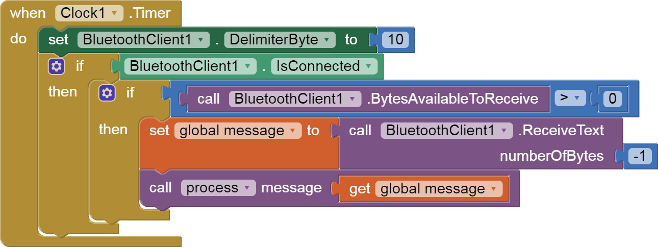

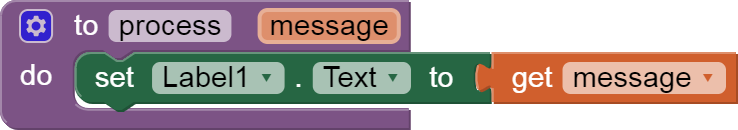
(draggable)
The delimiter byte can be set in the Designer instead, for efficiency.
Regarding your blocks:
- Image Pictures are usually file names, not colors.
- Don't draw a line if no data arrived on this clock cycle.
- Add the incoming data values as items to an array if you want to count values later
- Set your line color when each data has been captured into a variable, before you draw the next line.
- Each time you do a ReceiveText, you discard the previous received value, so receive into a variable and do all your multiple tests on that variable before asking for the next input.
- The ListPicker.AfterPicking event is not the place to check values of incoming data. Instead, do that in the Clock Timer's processing.