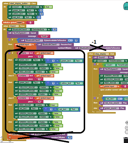
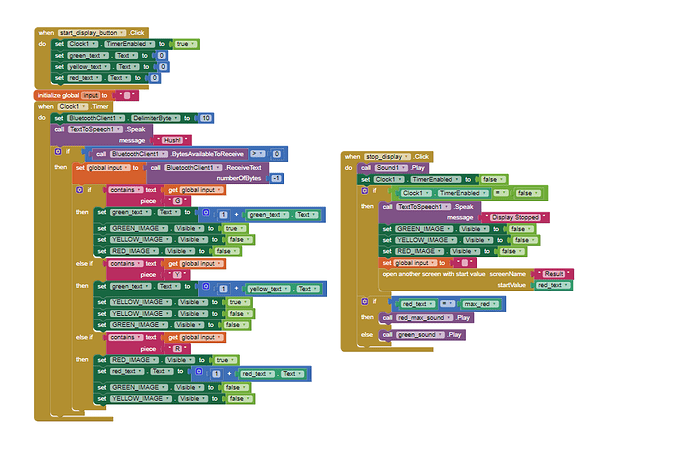
Display Different colors based on data received via bluetooth from sound sensor

Hello Everyone,

I'm working on a project that reads sound intensity via a sound sensor connected to an Arduino and transmits the data in decimal to the MIT app inventor. I would like for the app to display different colors based on the intensity. For instance Intensity 0-300 = green, 301-500 = yellow, and 501+ = red. I would also like to record the number of times a color is displayed within a certain interval and have the data available to the user once the color display is exited. My current code allows us to connect via Bluetooth but I'm having trouble displaying the colors.

How do I receive and organize the data coming in to the three color arrays?

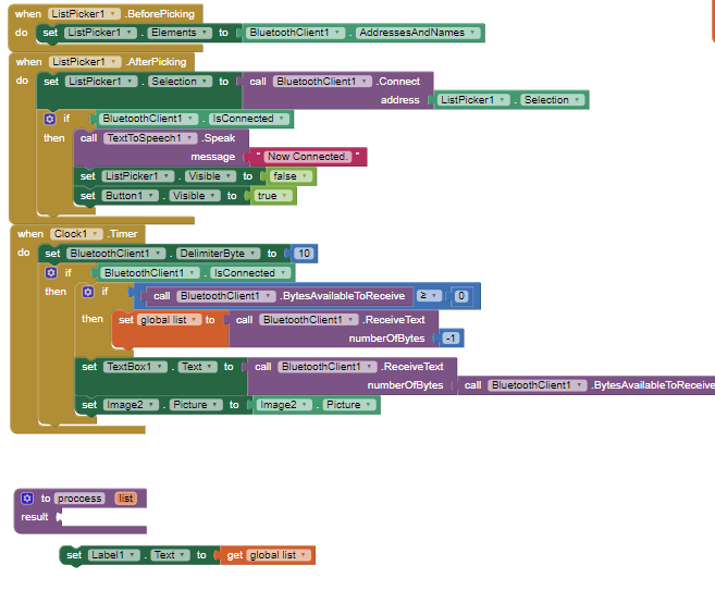
here is a snippet of my current blocks. Anything helps and thank you in advance!


1 Like

You should post your Arduino code here too, so we can verify you are sending text.

Here are the general rules for receiving text data values in BlueTooth ...

Please see the Delimiter article in FAQ

Be sure to use println() at the end of each message to send from the sending device, to signal end of message. Do not rely on timing for this, which is unreliable.

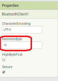
In the AI2 Designer, set the Delimiter attribute of the BlueTooth Client component to 10 to recognize the End of Line character.
Also, return data is not immediately available after sending a request,
you have to start a Clock Timer repeating and watch for its arrival in the Clock Timer event. The repeat rate of the Clock Timer should be faster than the transmission rate in the sending device, to not flood the AI2 buffers.

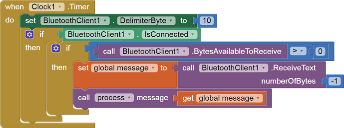
In your Clock Timer, you should check

  Is the BlueTooth Client still Connected?
  Is Bytes Available > 0?
     IF Bytes Available > 0 THEN
       set message var  to BT.ReceiveText(-1) 

This takes advantage of a special case in the ReceiveText block:

ReceiveText(numberOfBytes)
Receive text from the connected Bluetooth device. If numberOfBytes is less than 0, read until a delimiter byte value is received.

If you are sending multiple data values per message separated by | or comma, have your message split into a local or global variable for inspection before trying to select list items from it. Test if (length of list(split list result) >= expected list length) before doing any select list item operations, to avoid taking a long walk on a short pier. This bulletproofing is necessary in case your sending device sneaks in some commentary messages with the data values.
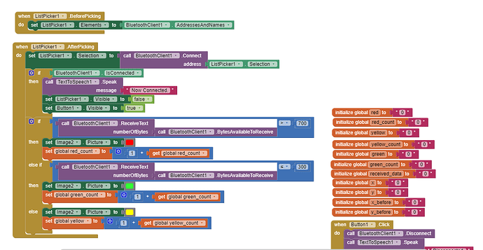
Sample blocks:


global message
(draggable)

The delimiter byte can be set in the Designer instead, for efficiency.

Regarding your blocks:

  • Image Pictures are usually file names, not colors.
  • Don't draw a line if no data arrived on this clock cycle.
  • Add the incoming data values as items to an array if you want to count values later
  • Set your line color when each data has been captured into a variable, before you draw the next line.
  • Each time you do a ReceiveText, you discard the previous received value, so receive into a variable and do all your multiple tests on that variable before asking for the next input.
  • The ListPicker.AfterPicking event is not the place to check values of incoming data. Instead, do that in the Clock Timer's processing.
1 Like

Thank you for your help!

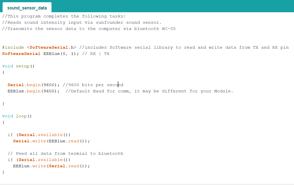
Here is my Arduino code. I'm just using the serial library and sending the serial input from the sensor.

I usually see print and println statements sending BlueTooth text to AI2 on this board.

Have you received data from this device on a terminal app yet to verify your data stream?

1 Like

Sorry for the late response. Thank you for your patience.

im unsure if data is coming through, because my phone is not working so i cant use the companion to see what i am doing. my partner is still waiting for the sensor to arrive so she hasn't been able to test yet. working on projects with groups is difficult during covid.

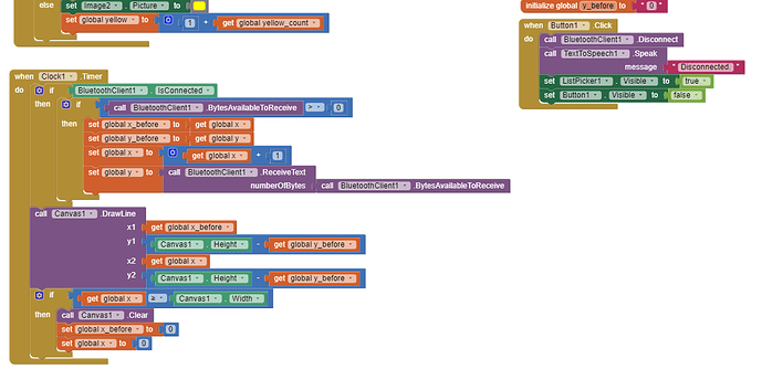
i tried to copy your code block for process but my configuration is a bit different from yours. the pieces dont seem to fit.
![image|432x158]
(upload://u4r5D5DStkk9J8o2gPY2icCDdWx.png)

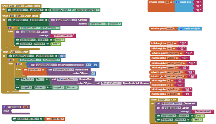
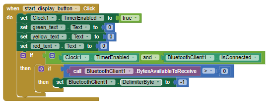
this is my current code blocks

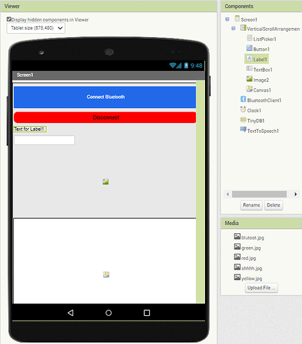
and my design

I decided to remove the line graph portion and focus on the image displaying and collection of data first so I uploaded pictures for the colors red yellow and green. So in the clock is where i check my values, increment data into an array, and set image to the uploaded pictures?

You have created a software UART on pins 0 and 1, which is the hardware UART on. Use other pins and connect BT to these pins.
There is also a bug in the main loop of arduino. The first condition should be: "if (EEBblue.avalible ())"

1 Like

UART? so i can just use other analog pins for tx and rx?

The built-in uart is on pins 0 and 1. But you use this uart to send data from the terminal to the arduino, and you can't connect anything else to the uart. Therefore, a second virtual uart port is created. It is declared at the beginning of the program. Right where you have (0, 1). Enter other pin numbers there and connect the bt module to them. Rx pin from bt module to Tx pin in arduino. Tx pin from bt module to Rx pin in arduino.

1 Like

You can write e.g. (5, 6) in script arduino. Then pin5 is RX and you connect TX pin with bt to it. Pin6 is TX and you connect RX with bt to it.
Then the arduino side will be fine and you need to improve the appinventor side program.

1 Like

ah, i am reading up on UART. I think i am understanding what youre saying

thank you for your input.

on the app inventor side, how do i create and increment the array of data and display the appropriate image for my project? im not sure if you say my current code blocks but here it is again

I think you would make changes to the arduino first. Then he tested the connection to the app. But in the app, make changes to the clock block.

  1. Now you have "bytesAvalibleToReceives> = 0", change to "bytesAvalibleToReceives> 0"

  2. You are reading all bytes as text. If you read everything, the second block of read tekst will have nothing to read. Consider what the data sent to the application will look like?

For testing, do this:


1 Like

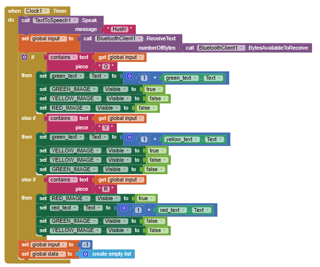
Here's where I'm at now:

The data from the sensor/arduino work properly: i labeled the values coming in with an R,Y,&G depending on the magnitude, then on app inventor i set up the clock and inside it, when a value is detected with an R,Y,or G an image with the appropriate color will be made visible, then made invisible once the value is changed. Something is wrong with my loop and it only stays the green image. can anyone help me troubleshoot this?

You are not splitting the incoming messages individually, so that is causing your Clock1.Timer IF/THEN/ELSEIf cascade to pick up only the first R/Y/G letter in the input chunk. (I would not call it a message until it is delimitted.)

Also, I recommend setting the other 2 images invisible in each if/then/elseif branch, instead of afterwards. It's simpler and more direct.

Here's the standard BlueTooth Delimiter advice ...

Please see the Delimiter article in FAQ

Be sure to use println() at the end of each message to send from the sending device, to signal end of message. Do not rely on timing for this, which is unreliable.

In the AI2 Designer, set the Delimiter attribute of the BlueTooth Client component to 10 to recognize the End of Line character.
BlueToothClient1_Properties

Also, return data is not immediately available after sending a request,
you have to start a Clock Timer repeating and watch for its arrival in the Clock Timer event. The repeat rate of the Clock Timer should be faster than the transmission rate in the sending device, to not flood the AI2 buffers.

In your Clock Timer, you should check

  Is the BlueTooth Client still Connected?
  Is Bytes Available > 0?
     IF Bytes Available > 0 THEN
       set message var  to BT.ReceiveText(-1) 

This takes advantage of a special case in the ReceiveText block:

ReceiveText(numberOfBytes)
Receive text from the connected Bluetooth device. If numberOfBytes is less than 0, read until a delimiter byte value is received.

If you are sending multiple data values per message separated by | or comma, have your message split into a local or global variable for inspection before trying to select list items from it. Test if (length of list(split list result) >= expected list length) before doing any select list item operations, to avoid taking a long walk on a short pier. This bulletproofing is necessary in case your sending device sneaks in some commentary messages with the data values.
I triple checked my arduino code and i confirmed i am using println(). I moved the visibility blocksto the same if else blocks. Now the delimiter placement is where im unsure.

So i set the delimiter byte to negative one here when the start display button is hit and the clock timer & bluetooth is enabledimage

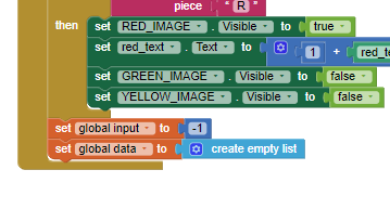
at the end of my when timer cascade i just need to set my message variable global data to -1?


image

The Delimiter Byte should be set to 10. 10 = New Line in ASCII.


global message
(draggable)

You could also just set it in the Designer Attributes of the BlueTooth Client component just once.

I see,

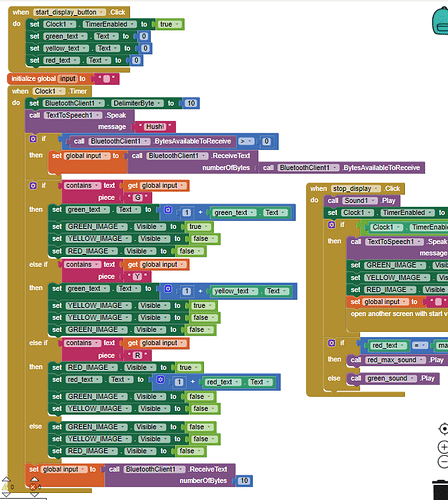
I changed my delimiter byte to ten at the beginning of the clock timer then set my variable equal to the delimiter byte

but now the app shuts down once I press the start button. perhaps it is getting the values too rapidly? how do i implement a delay on the app inventor side? I tried a delay on the arduino side but it ruins the functionality of my code and the values being sent.

f6b9a4354ce6b81c2ab274710fae63b52a358ed2_2_448x500

(tearing out hair)

Thank you for your patience.

Like so?

It doesnt shut down now, but all the still visible