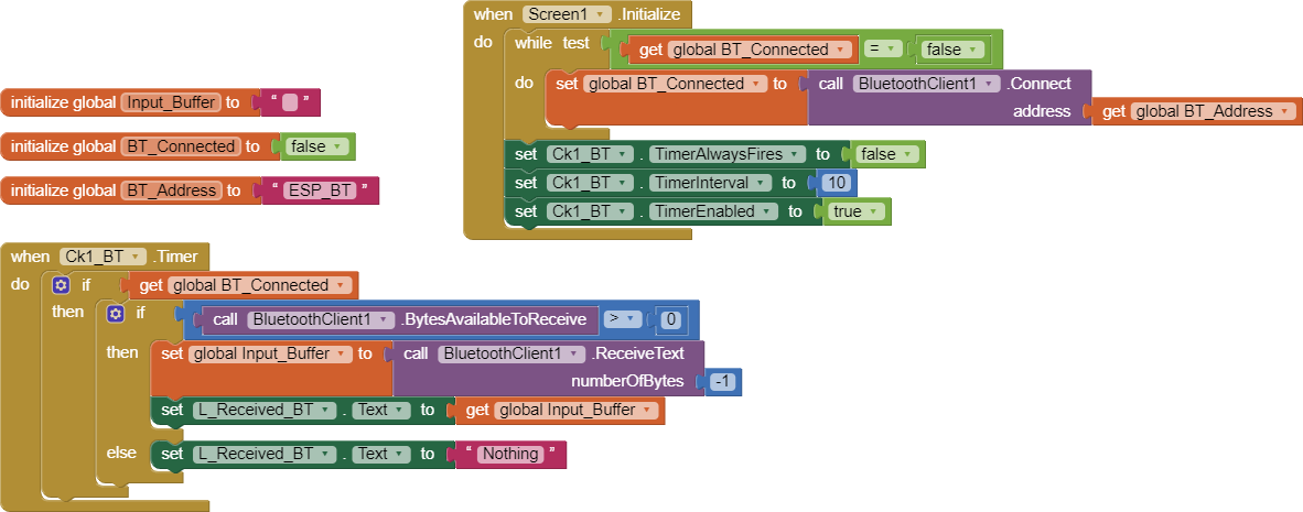
Hi, I tried to successfully resolve the issues, but my problem is that I can receive data from Arduino to my apps, and the timer is automatic even though there is no data to receive. If you need any assistance, I've attached the code and my MIT file.
char Incoming_value = 0;
char timed = 100;

void setup()
{
  Serial.begin(9600);
  pinMode(12, OUTPUT);
}

void loop()
{
  if(Serial.available() > 0)
  {
    Incoming_value = Serial.read();
    Serial.print(Incoming_value);
    Serial.print("\n");
    if(Incoming_value == '1'){
      digitalWrite(12, HIGH);
      delay(10000);
      Serial.println(timed);
    }

  }
}
Smart_Locker.aia (39.0 KB)
Welcome to the Community.
Though it is not pretty clear to me what you need, I had a look to your .aia and I could suggest you some hints:
- for clock1 and clock 2 you should disable, at design level, both "enabled" and "always fires": this avoids the clocks to still work even in background.
- in the event "screen 1 initialize" you should instantiate the blocks "timer interval " at the period you want for both timers, and after those two blocks, you should enable them.
- Then, if you want to stop a timer you can disable it when it has finished its job, and re-enable it when you need it again.
In your Arduino file, you use the Serial line for both BT and Serial Monitor ? This should be avoided as well, because it's better to have different serial lines: one dedicated to the BT and another one dedicated to the Serial Monitor (if you need it). What Arduino board are you using ? and what BT shield, if any (or the BT is integrated in the Arduino board itself ) ?
Depending on your Arduino board the delay() function can stop the CPU without leaving the possibility to do other tasks, like a serial Tx or Rx, therefore it could be better to use something like:
#define WANTED_TIMEOUT 10000
unsigned long timeout;
timeout = millis();
while ((mills() - timeout) < WANTED_DELAY) yield();
PS in your app, the clock2 where is used ?
1 Like
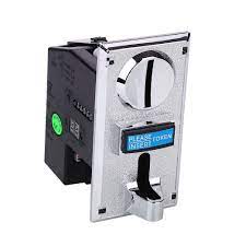
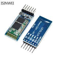
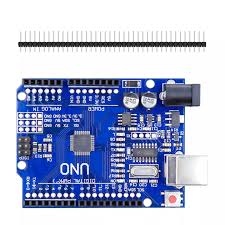
Thank you for your reply. By the way, this is my first time building a school project, and I've been using an Arduino Uno, a coin slot, and a HC-05 Bluetooth module for my communication. The term that we need to comply with for this project is "build an Arduino-based project with IoT support.
requirements :
- MIT apps should have a function after connecting to Bluetooth that, once the user clicks the button, sends data to the Arduino to enable the coinslot.
- Arduino Uno will collect the pulse of each coinslot; every pulse is equivalent to 1 minute. For example, if the user drops 2 coinslots, Arduino will send the pulse for 2 minutes in MIT apps.
- Once the time is up, it will notify the user and send the command to Arduino to disable the coinslot, unless the user clicks the button to start a new session.
- The MIT application should have user registration and sign-in.
Dear @Unknown_Source,
since it is a school project, as you can easily understand, I cannot make it for you :-).
Anyway, your requirements are quite clear, now.
My first suggestion is to do a search in the web sites of @Juan_Antonio (App inventor. Basic4Android. B4A. Estación meteorológica. Elastix. PHP MySQL.)
or @ChrisWard (https://www.professorcad.co.uk/)
Both sites are plenty of examples related to Arduino and BT communication toward AI2.
Luckily by using the UNO with a HC05 is the most simple way to start (BLE and other BT shields are much more complicated  ).
).
I'm pretty sure that by looking to those sites you'll find the 90% of the solution already made.
Anyway, please remember what I said in my previous answer: try to avoid to use the same Serial for both BT and Monitor (for example you can use the library SoftwareSerial -max speed 38400 for the BT and leave the Tx and Rx pins free for the Serial Monitor). Remember to cross the wires between the UNO and the Shield (Tx to Rx and visa versa). ***** Pls see my post below *****
Preferably do use the "send and receive text" blocks in the AI2 app, instead of sending and receiving bytes, because it's fast and robust enough. In the app you can use a fast clock, to be capable to catch any message sent by the Arduino board, and in that clock, wait until the terminator character (the LineFeed, i.e. the 0x0A - ASCII Char) is received, This means that the last transmission from Arduino to the app, must be done with a .println() (and not only a print() ) so the app can detect the end of frame.
Here below an example:
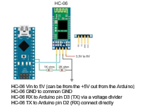
The following image shows a NANO with a HC06, but the principle is the same for UNO and HC05.
BTW, shoud you need further help, don't hesitate.
Best wishes !
2 Likes
Thank you for enlightening me, and you patiently and understandably explained it; I guess I got enough information from you, and thank you for the additional tags and samples; they helped a lot in my journey. thank you appreciated
Dear @Unknown_Source,
should the above information and those you can find into the two web sites not enough to get rid of your problem, please do not hesitate to ask me again.
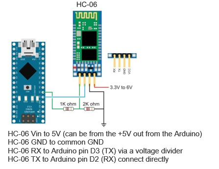
BTW, I've seen that the second picture is more or less unreadable, therefore i've annexed a better one here below:
And I have also to amend one information of my previous answer: it is the HC05 that is working @3.3 V, therefore the voltage divider shall be on the Rx pin of the HC05. Anyway, if you follow the drawing, you are on the safe side and, as I told, it is not mandatory, though preferable.
Sorry for that wrong info and best wishes !