Arduino Button check in a MIT APP

Hello Everyone.

First thing, Sorry, because my english is not so strong.
I made a App, that i can remote Electrohydraulic funtions on my Field Sprayer . I found a Arduino code on the Internet, and i modifed to my sprayer. Now i can use the App, with the arudino via Bluetooth. I want to got, data from two button ( when the button close the Circuit, at that time i can see On the App, because a Picture change.) I want to got Check from two parts on the Sprayer. Someone can help to me? unfortunately, i do not know the Arduino codes, and the App Inventor in this level( i am begginer)

Dávid

Hello David

You can write your posts in your native language, we can Google Translate.

However, a picture 'paints a thousand words' - could you draw a diagram of what you are trying to do?

Hello ChrisWard

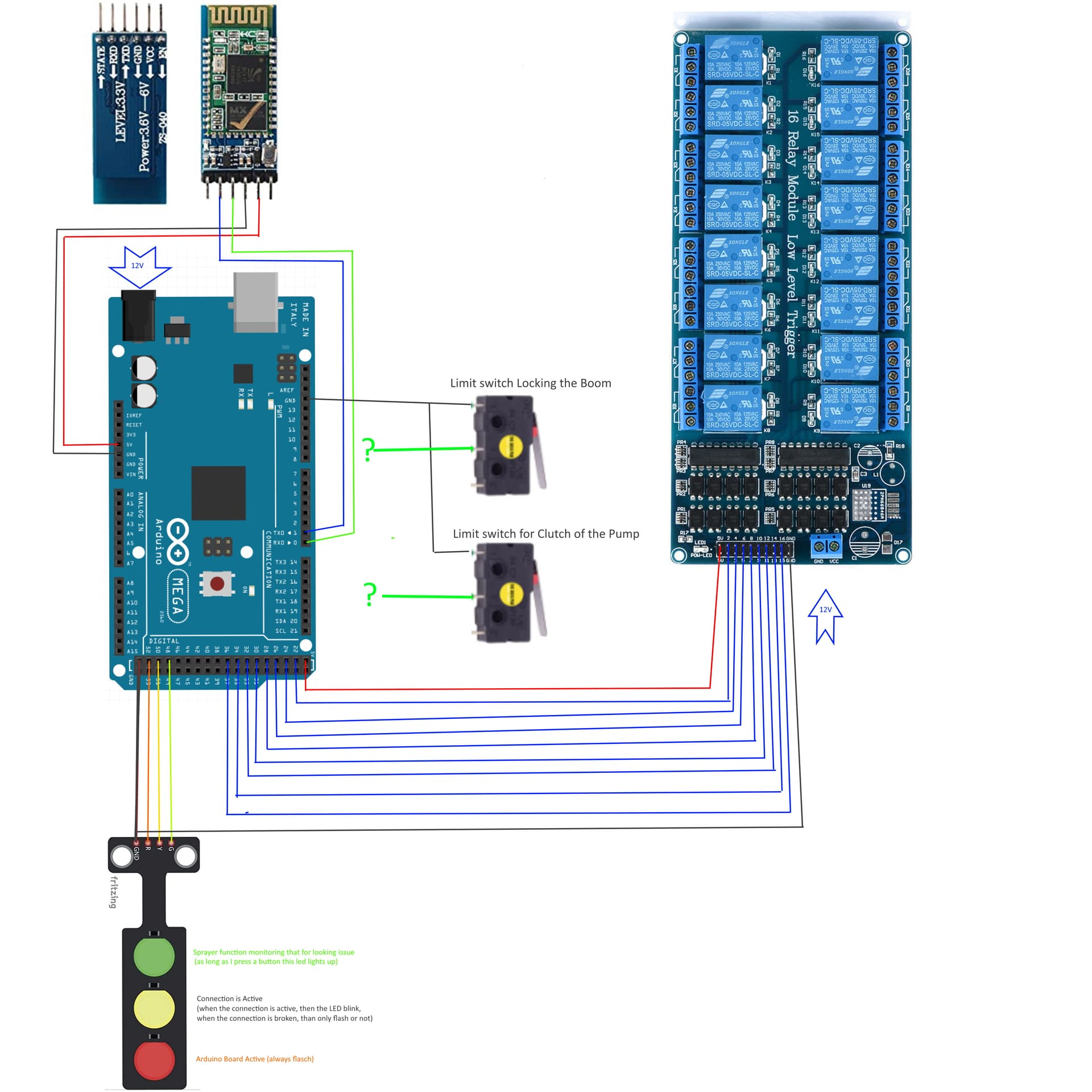
So, i made a Aplication for my Phone, and now i can remote my Field trailed Sprayer, because the original Controller is very big, and it has many Problem. I made the app, and when i touchdown the "button"than a Relay on the relay Board is in the On and the Funcion on the Boom is funcion( Sprayer boom up-down, ....) , when i let go the "button" then the Relay is swiching in Off, and the funcion of Boom is stopping. Now this wokrs with Sprayer all Functions ( Boom up-down, Boom rotate left- right, Folding and unfolding the boom, Worklight On-OFF, Clucth of the Sprayer Pump On-Off).
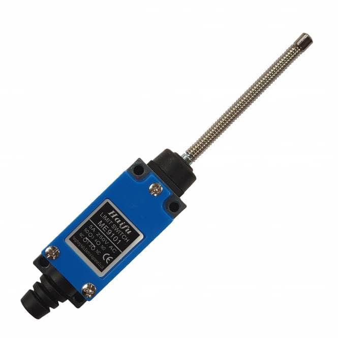
I want to Two Limit Switch on the Sprayer, that i can monitoring on the Phone, that the Clucht of the Sprayer Boom is in ON, and the other, that Boom is in the Good place for the Folding, or Unfolding.
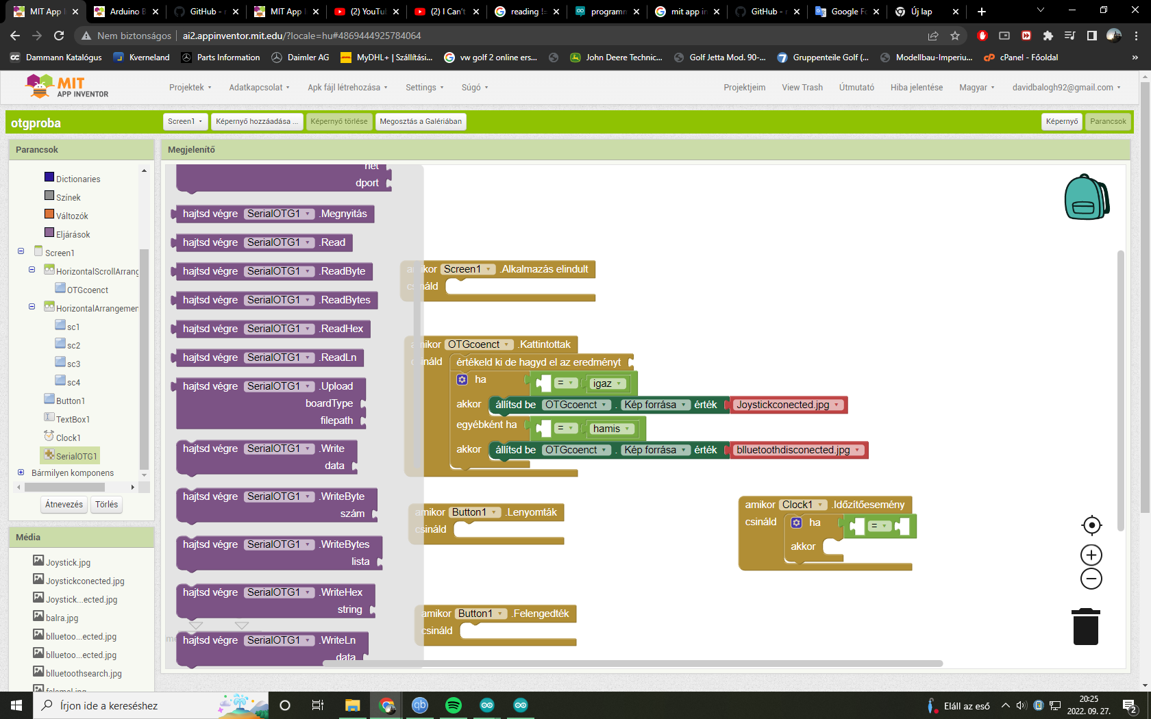
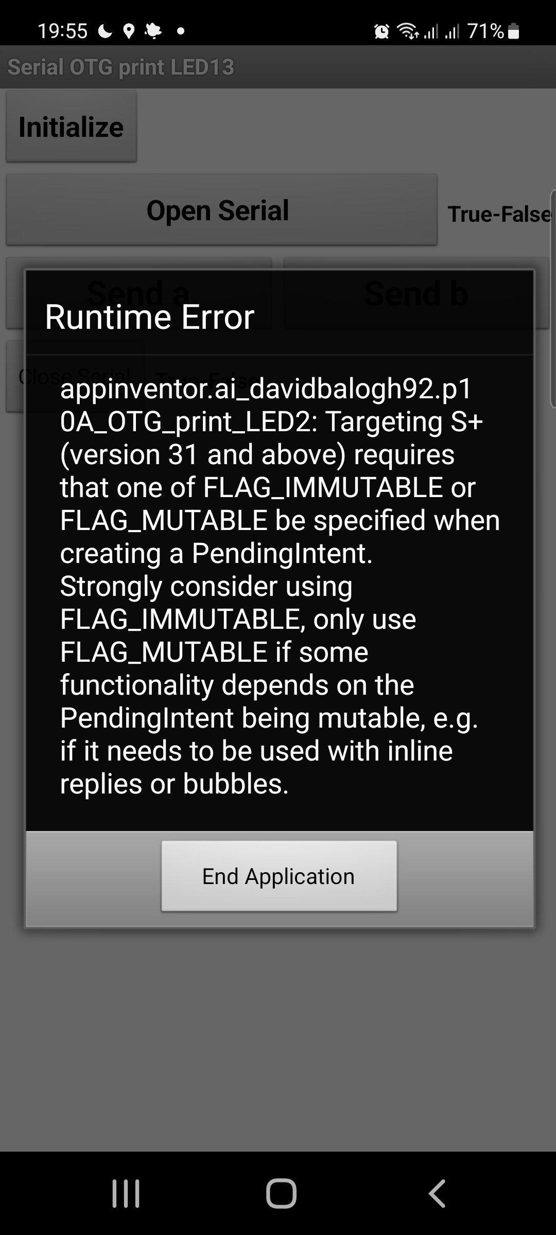
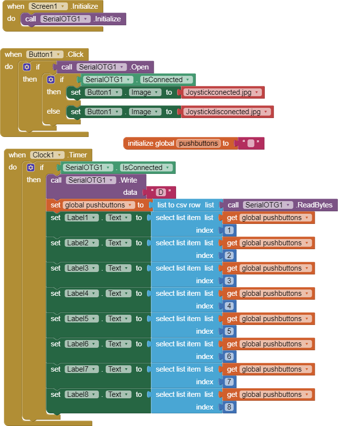
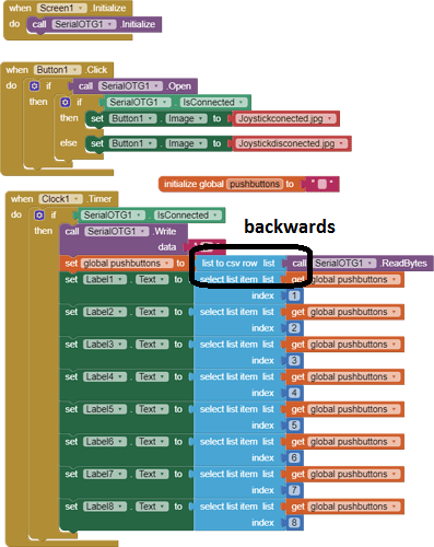
And this is my Problem, because, i made the Controlling, but i dont know, how i make the monitoring( In the arduino Code and in the MIT Blocks).
Here is the APP

Sprayer_Controller_v3.aia (827.8 KB)
I made a Shematich circuit.

Arduino code:

char Incoming_value = 0;


void setup() 
{
  Serial.begin(9600);         
  pinMode(22, OUTPUT);
  pinMode(23, OUTPUT);
  pinMode(24, OUTPUT);
  pinMode(25, OUTPUT);
  pinMode(26, OUTPUT);
  pinMode(27, OUTPUT);
  pinMode(28, OUTPUT);
  pinMode(29, OUTPUT);
  pinMode(30, OUTPUT);
  pinMode(30, OUTPUT);
  pinMode(31, OUTPUT);
  pinMode(32, OUTPUT);
  pinMode(33, OUTPUT);
  pinMode(34, OUTPUT);
  pinMode(35, OUTPUT);  // hidraulika kimenetek

  pinMode(36, OUTPUT);  // munka lámpa
  pinMode(37, OUTPUT);  // bal táblaszél szóró
  pinMode(38, OUTPUT);  //jobb táblaszél szóró
  
  
  pinMode(49, OUTPUT);
  pinMode(51, OUTPUT);
  pinMode(53, OUTPUT);


}

void loop()
{   
  digitalWrite(53, HIGH);  //Ardino ĂĽzemel
  
  if(Serial.available() > 0)  
 
  {
    Incoming_value = Serial.read();      
    Serial.print(Incoming_value);        
    Serial.print("\n");        
    if(Incoming_value == '0')             
      digitalWrite(22, HIGH);  
    else if(Incoming_value == '1') // Felemel      
      digitalWrite(22, LOW);   
      
      if(Incoming_value == '2')             
      digitalWrite(23, HIGH);  
    else if(Incoming_value == '3')       // Leenged
      digitalWrite(23, LOW);
      
      if(Incoming_value == '4')             
      digitalWrite(24, HIGH);  
    else if(Incoming_value == '5')       // Balra dönt
      digitalWrite(24, LOW);
      
      if(Incoming_value == '6')          //Jobbra dönt   
      digitalWrite(25, HIGH);  
    else if(Incoming_value == '7')       
      digitalWrite(25, LOW);
      
      if(Incoming_value == '8')        //Retesz be     
      digitalWrite(26, HIGH);  
    else if(Incoming_value == '9')       
      digitalWrite(26, LOW);
      
      if(Incoming_value == 'a')         //Retesz ki     
      digitalWrite(27, HIGH);  
    else if(Incoming_value == 'A')       
      digitalWrite(27, LOW);
      
    if(Incoming_value == 'b')            //  SzivattyĂş be
      digitalWrite(28, HIGH);  
    else if(Incoming_value == 'B')    
      digitalWrite(28, LOW);
           
    if(Incoming_value == 'c')            // SzivattyĂş ki
      digitalWrite(29, HIGH);  
    else if(Incoming_value == 'C')    
      digitalWrite(29, LOW);
           
    if(Incoming_value == 'd')            // Bal keret nyit
      digitalWrite(30, HIGH);  
    else if(Incoming_value == 'D')    
      digitalWrite(30, LOW);
            
      if(Incoming_value == 'e')         //Bal keret csuk
      digitalWrite(31, HIGH);  
    else if(Incoming_value == 'E')       
      digitalWrite(31, LOW);
      
    if(Incoming_value == 'g')            //  Jobb keret nyit
      digitalWrite(32, HIGH);  
    else if(Incoming_value == 'G')    
      digitalWrite(32, LOW);
           
    if(Incoming_value == 'h')            // Jobb keret csuk
      digitalWrite(33, HIGH);  
    else if(Incoming_value == 'H')    
      digitalWrite(33, LOW);
           
    if(Incoming_value == 'i')            // Nagy keret nyit
      digitalWrite(34, HIGH);  
    else if(Incoming_value == 'I')    
      digitalWrite(34, LOW);
                 
    if(Incoming_value == 'j')            // Nagy keret csuk
      digitalWrite(35, HIGH);  
    else if(Incoming_value == 'J')    
      digitalWrite(35, LOW);
// elektromos részek
           
    if(Incoming_value == 'k')            // Munka lámpa
      digitalWrite(36, HIGH);  
    else if(Incoming_value == 'K')    
      digitalWrite(36, LOW);
           
    if(Incoming_value == 'l')            // Bal táblaszél szóró
      digitalWrite(34, HIGH);  
    else if(Incoming_value == 'L')    
      digitalWrite(34, LOW);
                 
    if(Incoming_value == 'm')            // Jobb táblaszél szóró
      digitalWrite(35, HIGH);  
    else if(Incoming_value == 'M')    
      digitalWrite(35, LOW);


// ellenörző szervek

         if(Incoming_value == 'w')              // Kapcsolat kész
      digitalWrite(49, HIGH);  
    else if(Incoming_value == 'W')      
      digitalWrite(49, LOW);
     
      if(Incoming_value == 'q')        // Művelet visszajelző     
      digitalWrite(51, HIGH);  
    else if(Incoming_value == 'Q')       
      digitalWrite(51, LOW);
      
   
}


   }

Limit Switches are used for CNC machines and so you can just Google Search for how to do that, you will find plenty of information.

Connect a second Serial for the App to receive signals from the Limit Switches via the HC-05.

Just because i wrote the limit switch, because, this is on the agricultural maschine ( see the Picture)

. To me is important, only if the button/switch close the circuit, i see it.
Did you mean this Serial? If yea, unfortinatly i do not know it.
I write the ARduino code, like if i try the Data write on the Serial Monitor in the Arduino IDE?

Sorry if i am very slow brain man.

Currently, you are sending commands to the Arduino via Bluetooth and the Arduino is waiting for those incoming commands (values) via a hardware Serial Channel. It needs a second Serial Channel connected to send the Limit Switch signals to the App. Your Arduino Mega has four Serial Channels available.

So, as I said in my previous post, search Google for examples of CNC machines using Arduino as they will show you how to wire-up Limit Switches.

Here Arduino UNO, HC-06 BT, two potentiometers.

A Timer in App Inventor continually queries for its values.

https://community.appinventor.mit.edu/t/bluetooth-hc-06-arduino-send-receive-send-text-file-multitouch-image/9518/8

Here two Push Button

https://community.appinventor.mit.edu/t/bluetooth-hc-06-arduino-send-receive-send-text-file-multitouch-image/9518/7

Maybe you can get some ideas.

thanks for the help, because now the Arduino can a indication back to me in to the App.
For a another test, i want to got indicate from the Arduino, but, via OTG. I want to make a Joystick. The arduino code is "done", and i trty to tesst, in the serial monitor, than there is everything good. I have tried the data recevied in the App, ( The Serial blocks looked, like Bluetooth variant) but not worked. Someone can help to me , how can i the Blocks made? Or can give me a examlpe.

Arduino code:

const int buttonPin7 = 7;
const int buttonPin8 = 8; // the number of the pushbutton pin
int buttonState7;
int lastButtonState7;
int buttonState8;
int lastButtonState8;
String Bt;

void setup()
{

pinMode(buttonPin7, INPUT);
pinMode(buttonPin8, INPUT);// initialize the pushbutton pin as an input
Serial.begin(9600);
}

void loop()

{
{delay(5);

int reading = digitalRead(buttonPin7);
if (reading != lastButtonState7)
{
if (reading == 1)
{ Bt = "FEL1";
Serial.print(Bt);
}
if (reading == 0)
{ Bt = "FEL2";
Serial.print(Bt);
}

}
lastButtonState7 = reading;
}
int reading = digitalRead(buttonPin8);
if (reading != lastButtonState8)
{
if (reading == 1)
{ Bt = "LE1";
Serial.print(Bt);
}
if (reading == 0)
{ Bt = "LE2";
Serial.print(Bt);
}

}
lastButtonState8 = reading;
}

OTG, try this extension:

Hello,

I tried the OTG extension, but i dont know why, i did not can chose the SerialPrint Block, and on the Desinger site, i cant set the Buffer size. What is the wrong.
But when i downloaded, your aia file, and tested, than there everithing is okaywith the OTG extension, only, if i import the extension than wrong.
My import.


Your app if i import to MIT

And the desinger site in my app

Try with
Write
and
WriteLn

Hello,
Can you help me, because when i problay mde a app, than i cant conected the Serial, for the Phone or tablet. I have a Samsung Galaxy S51 and a Tab S6 Lite. All of this two devices has OTG, i tested. But when i tried conected the Serial than i become this Error message all of twoo Devises.

That seems to be a bug in the extension that is not adapted to Android 12.

Maybe the author of the extension will decide to fix it.

Search this community about the FLAG_IMMUTABLE FLAG_MUTABLE error

When before you send me your Comment, then i looked in other Topics, and there i saw, this is a relative great problem. But thanks the answer.

Hello,
i tried the Data send from arduino via Otg. i do not find all of the blocks, like in yours App-s.
My app worked right, via Bluetooth, but i have to use on Otg. The Arduino code stayed the same like the bluetooth version. Can you help me, that what is wrong?

From what I can see, you are expecting an answer immediately after you send the request.
Please take a look at my documentation SerialOTG_1.4.pdf and examples:

“Remember that serial line communication is just a stream of bytes. There is no packet handling.
Each byte takes some time to transfer on the line. So if you send a request, then you have to wait for
a while, before you get an answer.
You have to add some kind of message handling yourself by timing, message length, content etc.

WriteLn(), ReadLn() implements a kind of message handling. It uses new line character to end an
UTF-8 message. Use ASCII char set (7-bit) to avoid problems if you communicate with Arduino.”

Have you tested the new version adapted to Android12, see Using serial with FTDI - #102 by Jambo ?

1 Like

Yeah , i tested with Android 12 ( Galaxy Tab S6 Lite) and i can data send to the Arduino. ( Led, on-off) , The device/app do not freez by me and it dont give Warning message to me.

Thanks, then I know.
I think the easiest way to communicate if you are not familiar with serial communication is by using writeln, readln, You can look at my examples ArduinoTime.aia, Time.ino to see how it works.

813f35e56d7b004ad477539ecbe565857c532fe0_2_397x500

Your csv to list conversion is backwards unnecessary. Does ReadBytes return a list of Bytes?

Also, it is wise to check length of list before attempting to select list items.

1 Like

I did not write in my before answer. When am i tested your new Extension for the OTG, than i used only the nb190 bugfixed MIT App Inventor.
http://nb190a-bugfixes.ai2-ewpatton-temp.appspot.com
I hope, that i linked right the URL.