Try to create the graph using MIT APP inventor

I am trying to create an app using MIT app inventor to show the ppg waveform of my pulse sensor. However, I did not succeed, now I can only show the BPM, but cannot show the waveform. Therefore, I am seeking help.

The code is shown below.
For MIT apps Inventor code:
Heart2020.aia (8.2 KB)

For Arduino code:
#include <SoftwareSerial.h>
SoftwareSerial HC06(2,3);
int UpperThreshold = 550;
int LowerThreshold = 490;
int reading = 0;
float BPM = 0.0;
bool IgnoreReading = false;
bool FirstPulseDetected = false;
unsigned long FirstPulseTime = 0;
unsigned long SecondPulseTime = 0;
unsigned long PulseInterval = 0;
const unsigned long delayTime = 10;
const unsigned long delayTime2 = 1000;
const unsigned long baudRate = 9600;
unsigned long previousMillis = 0;
unsigned long previousMillis2 = 0;

void setup(){
Serial.begin(baudRate);
HC06.begin(9600);
}
void loop(){
if (HC06.available()){
Serial.write(HC06.read());
}

//Write from Serial Monitor to HC06
if (Serial.available()){
HC06.write(Serial.read());
}

// Get current time
unsigned long currentMillis = millis();

// First event
if(myTimer1(delayTime, currentMillis) == 1){

reading = analogRead(0); 

// Heart beat leading edge detected.
if(reading > UpperThreshold && IgnoreReading == false){
  if(FirstPulseDetected == false){
    FirstPulseTime = millis();
    FirstPulseDetected = true;
  }
  else{
    SecondPulseTime = millis();
    PulseInterval = SecondPulseTime - FirstPulseTime;
    FirstPulseTime = SecondPulseTime;
  }
  IgnoreReading = true;
 
}

// Heart beat trailing edge detected.
if(reading < LowerThreshold && IgnoreReading == true){
  IgnoreReading = false;

}  

// Calculate Beats Per Minute.
BPM = (1.0/PulseInterval) * 60.0 * 1000;

}

// Second event
if(myTimer2(delayTime2, currentMillis) == 1){
Serial.print(reading);
Serial.print("\t");
Serial.print(PulseInterval);
Serial.print("\t");
Serial.print(BPM);
Serial.println(" BPM");
Serial.flush();
HC06.print(BPM);
HC06.print(" BPM");
HC06.print("/");
HC06.print(reading);

}
}

// First event timer
int myTimer1(long delayTime, long currentMillis){
if(currentMillis - previousMillis >= delayTime){previousMillis = currentMillis;return 1;}
else{return 0;}
}

// Second event timer
int myTimer2(long delayTime2, long currentMillis){
if(currentMillis - previousMillis2 >= delayTime2){previousMillis2 = currentMillis;return 1;}
else{return 0;}
}

Why do you have a button AND a clock that are receiving bytes.
This is going to interfere in strange ways I guess. Somehow I think that the button should not be there.

Also, set in the designer the delimiter byte attibute for the BluetoothClient to 10. Then, instead of reading bytes available, read -1 bytes. This will ensure that you always read complete messages from your Bluetooth device, provided that you end each message with a println();
Cheers, Ghica.

thank you for your guiding.
I have change some coding in MIT apps Inventor, however it doesn’t works. Could you please help me to change if u think the code is wrong? Because I am just a beginner in the coding world.
Actually, my project is going to make a connection with my heart beat sensor and the bluetooth to phone.


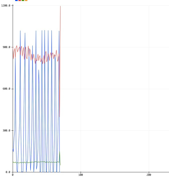
I want to show the waveform which is the blue line, to show it on the phone using MIT apps Inventor.

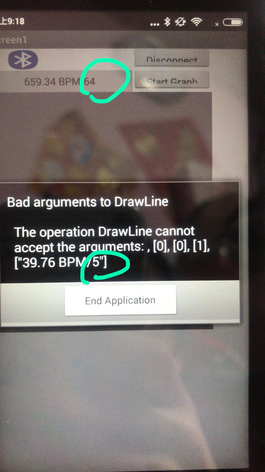
the value that was circled it the data value for the waveform

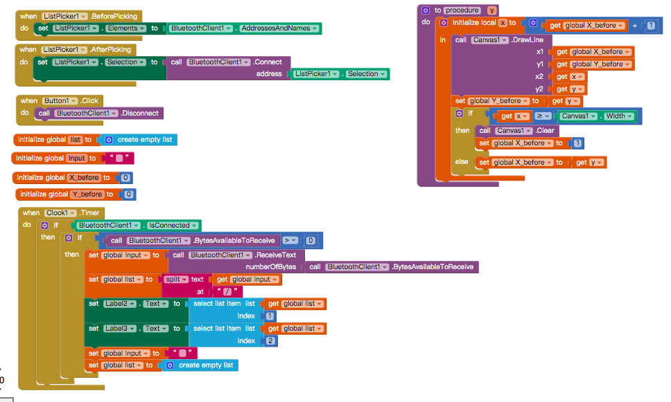
this is the code for the MIT apps Inventor, but actually dont know whether it is correct.
Also, how can I change the coding for Arduino in order to communicate with the code of MIT apps inventor to show the graph?
Here is my apps inventor code and Arduino code.
Heart2020 (1).aia (7.8 KB)

#include <SoftwareSerial.h>
SoftwareSerial HC06(2,3);
int UpperThreshold = 550;
int LowerThreshold = 490;
int reading = 0;
float BPM = 0.0;
bool IgnoreReading = false;
bool FirstPulseDetected = false;
unsigned long FirstPulseTime = 0;
unsigned long SecondPulseTime = 0;
unsigned long PulseInterval = 0;
const unsigned long delayTime = 10;
const unsigned long delayTime2 = 1000;
const unsigned long baudRate = 9600;
unsigned long previousMillis = 0;
unsigned long previousMillis2 = 0;
void setup(){
Serial.begin(baudRate);
HC06.begin(9600);
}
void loop(){
if (HC06.available()){
Serial.write(HC06.read());
}
//Write from Serial Monitor to HC06
if (Serial.available()){
HC06.write(Serial.read());
}
// Get current time
unsigned long currentMillis = millis();
// First event
if(myTimer1(delayTime, currentMillis) == 1){
reading = analogRead(0);
// Heart beat leading edge detected.
if(reading > UpperThreshold && IgnoreReading == false){
if(FirstPulseDetected == false){
FirstPulseTime = millis();
FirstPulseDetected = true;
}
else{
SecondPulseTime = millis();
PulseInterval = SecondPulseTime - FirstPulseTime;
FirstPulseTime = SecondPulseTime;
}
IgnoreReading = true;
}
// Heart beat trailing edge detected.
if(reading < LowerThreshold && IgnoreReading == true){
IgnoreReading = false;
}
// Calculate Beats Per Minute.
BPM = (1.0/PulseInterval) * 60.0 * 1000;
}
// Second event
if(myTimer2(delayTime2, currentMillis) == 1){
Serial.print(reading);
Serial.print("\t");
Serial.print(PulseInterval);
Serial.print("\t");
Serial.print(BPM);
Serial.println(" BPM");
Serial.flush();
HC06.print(BPM);
HC06.print(" BPM");
HC06.print("/");
HC06.println(reading);
}
}
// First event timer
int myTimer1(long delayTime, long currentMillis){
if(currentMillis - previousMillis >= delayTime){previousMillis = currentMillis;return 1;}
else{return 0;}
}
// Second event timer
int myTimer2(long delayTime2, long currentMillis){
if(currentMillis - previousMillis2 >= delayTime2){previousMillis2 = currentMillis;return 1;}
else{return 0;}
}

Thank you so much for your help!!!

The BPM and waveform are sent as a value [“39.76 BMP/5”] apparently. I expect you can split this data point into 39.76 and 5 . Use the split text block by splitting at ‘BMP/5’ which will result in a list of 39.76 and 5 . Graph each value separately.

image

split at " BMP/" (there is a space before B) to return 39.76 and 5