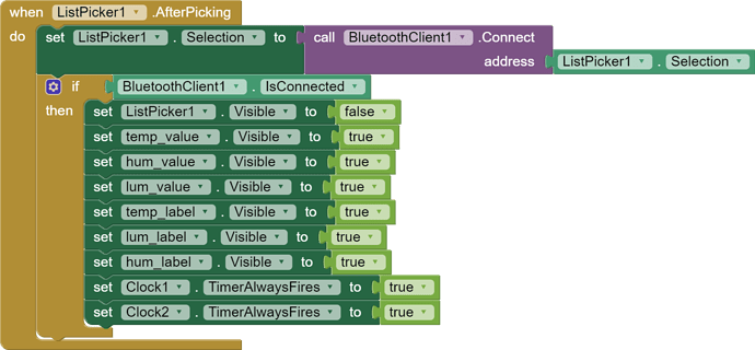
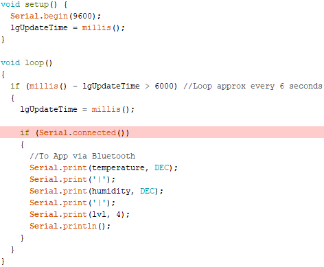
The sketch looks like this, but once again I am not sure about what I did. The "Serial.connected()" doesn't work, it says "class HardwareSerial has no member named connected". I tried Serial.available() but it does absolutely nothing. I defined temperature and humidity at the top as "byte temperature" and "byte humidity" is that correct? I've incluede the DHT library in the first place, that was not the problem ![]() . I've noticed that in the "Serial.print(lvl, 4)" line, the 4 is not "blue" like DEC or other stuff...
. I've noticed that in the "Serial.print(lvl, 4)" line, the 4 is not "blue" like DEC or other stuff...
Last thing. In my other sketch I was able to see the results in the serial monitor of arduino IDE, now I don't see anything.
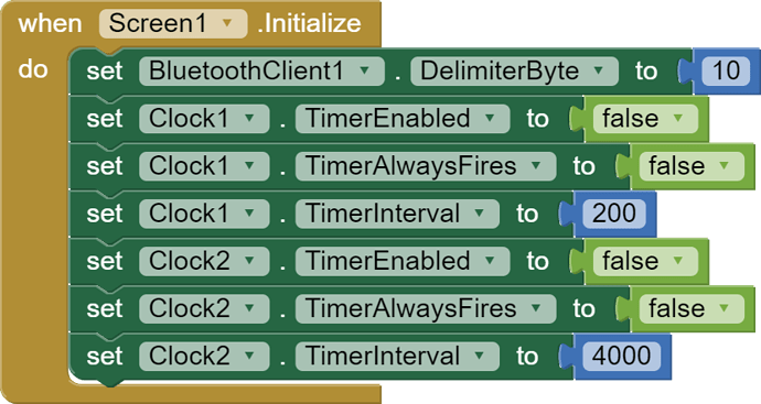
it should happen here, so after I pick a Bluetooth device to connect to but I am not sure how these clocks actually work
From the documentation of clock:
Properties
TimerAlwaysFires
Will fire even when application is not showing on the screen if true
TimerEnabled
Specifies whether the Timer event should run.
TimerInterval
Specifies the interval between subsequent Timer events.
Note: Drift may occur over time and that the system may not honor the timing specified here if the app or another process on the phone is busy.
I think you also must enable the timer.
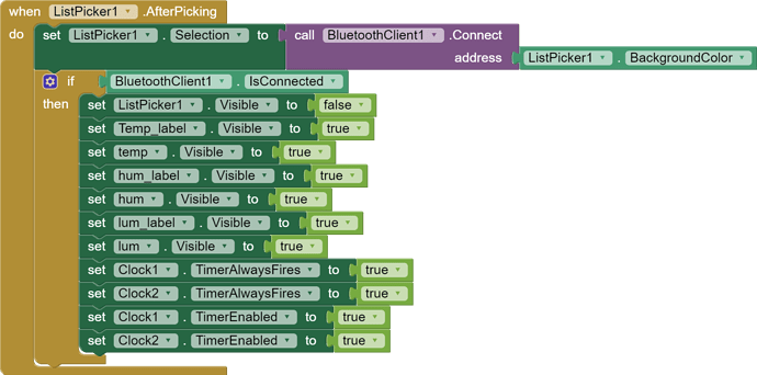
Hi! Thanks for joining the conversation. I enabled the timer like the image below. Is it right?
Absolutely nothing happen. No errors, no crashes, nothing. My HC-05 (the Bluetooth module on the breadboard) keeps flashing like it is sending info correctly but the app doesn't show the results.
The complete code is down here, am I not seeing the error?


Here is the arduino sketch too...
#include <SimpleDHT.h>
int pinDHT11 = 2;
SimpleDHT11 dht11;
#define light (A1)
int lvl;
unsigned long lgUpdateTime;
byte temperature;
byte humidity;
void setup() {
Serial.begin(9600);
lgUpdateTime = millis();
}
void loop()
{
if (millis() - lgUpdateTime > 6000) //Loop approx every 6 seconds
{
lgUpdateTime = millis();
if (Serial.connected())
{
  //To App via Bluetooth
  Serial.print(temperature, DEC);
  Serial.print('|');
  Serial.print(humidity, DEC);
  Serial.print('|');
  Serial.print(lvl, 4);
  Serial.println();
}
}
}
Sorry Noobie, I have been away, enjoying the delights a bug that's going around here. What Android device are you using, Make/Model?
They are enabled when required - there is an Example Project here (somewhere) ![]()
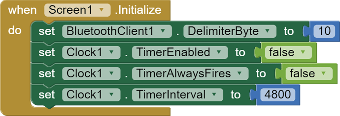
Noobie, post #4, what did I say about 'TimerAlwaysFires? It should not be enabled (true) in your App 
You are initialising two Clock Timers but only using one - it would help you to give them meaningful names as per my Example Project.
Why are your Labels hidden and why hide your ListPicker? If the App is just for your use and you want to do that, OK, but a GUI that changes mid-use is not really a good idea. Imagine that happening on a car dashboard...........
Concerning the 'other Timer' -that is to allow time for a connection to be made. It has solved the issue of not connecting for many people so I suggest you copy my example and use a Timer for connection.
In my example you will see how to assign the List Picker Selection to the Bluetooth Connection Address - what you have in the image above is, sorry to say, completely wrong.
More haste, less speed!
Thanks for the advice, I really appreciate it. I'll try to follow the path you gave me even if I'm walking in the dark. I really don't know how these blocks should be easy to merge in order to create a single app 
Nothing happened... no errors, no crashes. Just not showing the data.
I didn't hide labels and I kept one clock because I don't have connection problems.
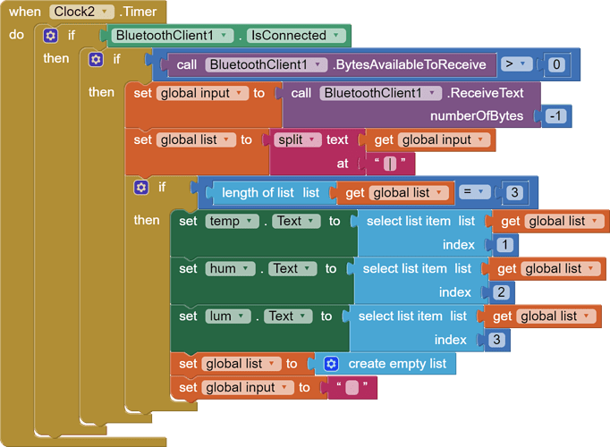
I've noticed that I need a "list" variable and a "input" variable, without one of them the code doesn't work at all. The new code is right below.


One more thing. "Serial.connected()" is not a thing in Arduino. I used my old sketch just to test the app. What should I used instead of "Serial.connected()" ?
Thanks for your patience by the way 


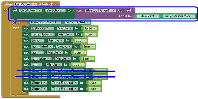
There is a bit missing from your Blocks, and this is wrong, similar to the way it was wrong before:
Let's dissect the error so you understand:
-
The Block 'set ListPicker Selection'. With this Block, the developer can programatically select an item in the List - it is then moved to become the first item in the List. This is intended for use with static lists, for example a list of different types of fruit or different types of cars. It's simply not appropriate for your App because until available devices have been scanned, you do not know what is in the list or where any particular device may be in the list.
-
On top of that, your Blocks attempt to change the selection with the value output by 'call Bluetooth Client Connect' - which is meaningless from the perspective of the list, as it is a 1 or 0 (True or False boolean).
-
Immediately after attempting to connect, the code will start Clock1 if the Bluetooth Client is connected - that leaves your connection down to luck alone because the test is too soon and if the test finds that the Bluetooth Client is not connected, the program stops working right there! So do you see:
You do have connection problems.
Unfortunately you have repeated the same mistake as before, when you could copy my code to get it right. In my code there is a note "Allow some time to Connect" and the Blocks within a Clock Timer make five connection attempts - if the connection was not achieved, the User is Notified.
Note, if you want the ListPicker Button to confirm to the User what has been picked:

The code could not work without both of them.
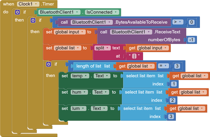
- The 'input' variable is used to store the data (a string of text) that arrives, via Bluetooth, from the Arduino.
- The 'list' variable is used to store the converted data, which initially looks like this, a single continuous string (of text):
value1|value2|value3
The string is converted (split-up) into a List:
value1
value2
value3
.... discarding the value delimiters ("|") and making it easy to test that all of the expected data, consisting of three values, has been received. If the List failed the test, perhaps one or all of the values had failed to arrive, no harm is done - the App continues and processes the next data packet on arrival.
Another thing you have missed in my example, in addition to reminding the User that the Arduino must be switched on, the phone's Bluetooth must be switched on and late versions of Android may require Location switched on, is this:
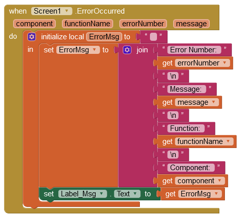
If an error occurs (perhaps silently or not noticed), knowing what error and the source is very valuable.
It is a thing, but only when Software Serial is being used (instead of or in addition to Arduino's built-in Serial Comms). So you can remove the the Serial Connected() test. Sorry, that's my bad.
I haven't used the 'SimpleDHT' library, which appears to be automatically delivering the values as integers (bytes). The standard DHT.h library delivers the values as floats. So if, after correcting your Blocks and testing again, you do not receive values in the App, do not perform a value type conversion in Serial on the DHT output:
Serial.print(temperature);
Serial.print("|");
Serial.print(humidity);
Serial.print("|");
Serial.print(lvl, 4); //4 decimal places
Serial.println();
Make sure the Text Colour is not the same as the Back Colour in the Value Labels!
Dear @Noobie ,
By looking to your Arduino code, a question arise to me: what kind of Arduino board and BT shield are you using ? And to which pins of the Arduino board are you connecting the shield ?
Please be aware that the serial.write() instruction drives the hardware serial line of the Arduino, and is used to communicate toward the PC monitor.
In other words if you haven't connected the BT shield to pins 0,1 of the Arduino board, but to other pins, you shall use the Softwareserial library instead. And connect the BT shield to pins 10,11 (typically). Please take a sight to my answer to another very similar topic:
Unless that you are really sure that the Arduino board is granted to send the data, you can break your head against the wall before having the AI2 code working... ![]()
Hoping it helps.
ciao, Ugo.
I wrote the code like below. Is the miBT thing right like that? I kept the Serial.print just because I can see if it is working and what I'm doing
#include <SimpleDHT.h>
#include <SoftwareSerial.h>
int pinDHT11 = 2;
SimpleDHT11 dht11;
#define light (A1)
int lvl;
SoftwareSerial miBT(0, 1);
byte temperature;
byte humidity;
void setup() {
Serial.begin(9600);
}
void loop(){
if(dht11.read(pinDHT11, &temperature, &humidity, NULL)){
return;
}
lvl=analogRead(light);
Serial.print(temperature, DEC);
Serial.print("|");
Serial.print(humidity, DEC);
Serial.print("|");
Serial.print(lvl);
Serial.println();
miBT.print(temperature);
miBT.print("|");
miBT.print(humidity);
miBT.print("|");
miBT.print(lvl);
miBT.println("|");
delay(6000);
}
Hello @Noobie,
if you use the SoftwareSerial library you can leave the pins 0,1 to the hardware serial to communicate toward the PC, and you shall re-allocate the miBT line on pins 10,11 (Rx, Tx), like this:
SoftwareSerial miBT(10, 11);
Obviously you have then to connect the BT shield to those pins (be sure to reverse the Arduino Tx to the HC05 Rx and visa versa).
In your setup() you shall then initialize the communication toward the shield, by coding: miBT.begin(38400);
This is typically the baudrate of the BT shield. Also in this case, please be aware that the SoftwareSerial library does not work properly with higher baudrates, so 38400 is the maximum speed that you can use satisfactorily (higher speeds can incur in framing errors).
The loop() seems correct.
Looking for the next step.
Ciao.
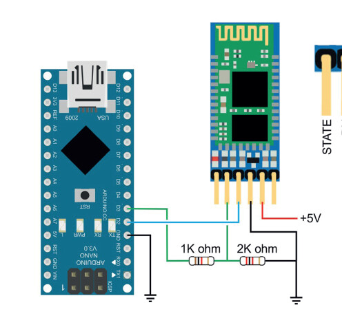
PS remember that the HC05 (or HC06) works preferably with a 3.3 V on its pins, so the Tx from Arduino toward the Rx of the shield, would preferably be reduced with a resistor partition, like the following :
The app still doesn't work at all. But the code works fine, no errors, no crashes...
What would happen if the Rx and Tx are reversed instead of being in the correct way?
And what can I do about the app in AI2?
By the way, I'm using a logic converter to convert the 5V to 3.3V. I wrote 3 before, but I intended 3.3V. I read that is preferable to use a logic converter instead of using resistors, is it right?
Dear @Noobie,
there is no need to use a voltage converter, a partition is more than enough. For sure if you dont cross the lines (Tx vs Rx) it won't work. But don't forget to separate the miBT from the hardware serial pins 0,1.
And initialize correctly the BT line in terms of pins and baudrate.
Cheers
Hi Noobie
If you are using Software Serial in addition to the board's, you need to identify the digital pins used and apply a name. You have used the name miBT which is fine, but if using an Arduino UNO for example, the Software Serial cannot use pins 0,1 - connect your Bluetooth Module to other pins and declare those in the Sketch -This is dependent on both the Arduino you have and the exact Software Serial Library, of which there are a few.
You still have not told us exactly what Arduino (and what chip, what board revision), what Bluetooth module and make/model of your Android Device you are using.
Hi ChrisWard. I'm using pin 10 and pin 11 (to be Rx and Tx) instead of 0 and 1.
I'm using a copy of Arduino UNO Rev3 (the actual name is Elegoo UNO R3) using a ATmega328P, a HC-05 and a Samsung Galaxy A52.
Sorry, I didn't read the request previously
Hi @Noobie,
the HW seems OK.
I would suggest also to remove the voltage adapter and to put two simple resistors (I don't know if the voltage converter has the ground properly connected or if it smoothes the edges of the serial line).
So please follow my hints. Be sure the pins are crossed (take a sight to the drawing) and initialize the library.
Before the setup instantiate the pins assignment
SoftwareSerial miBT(10, 11);
And in the setup the baudrate
void setup()
{
...
miBT.begin(38400);
...
...
}
...Just noticed you are using a Delay() in the Sketch Loop instead of elapsed time. 
I'll let you know what will happen following your hints, thank you
