NOWY.aia (12.6 KB)
There you go! 
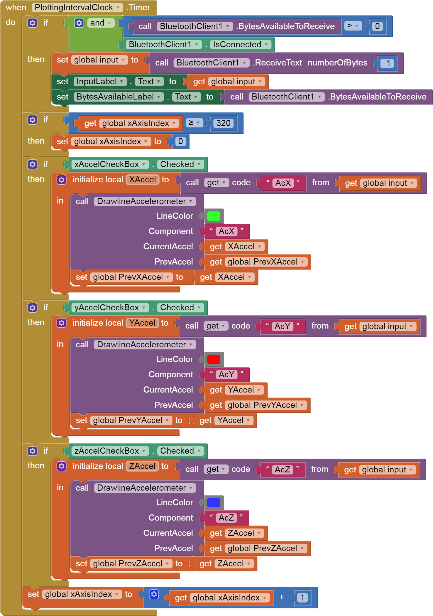
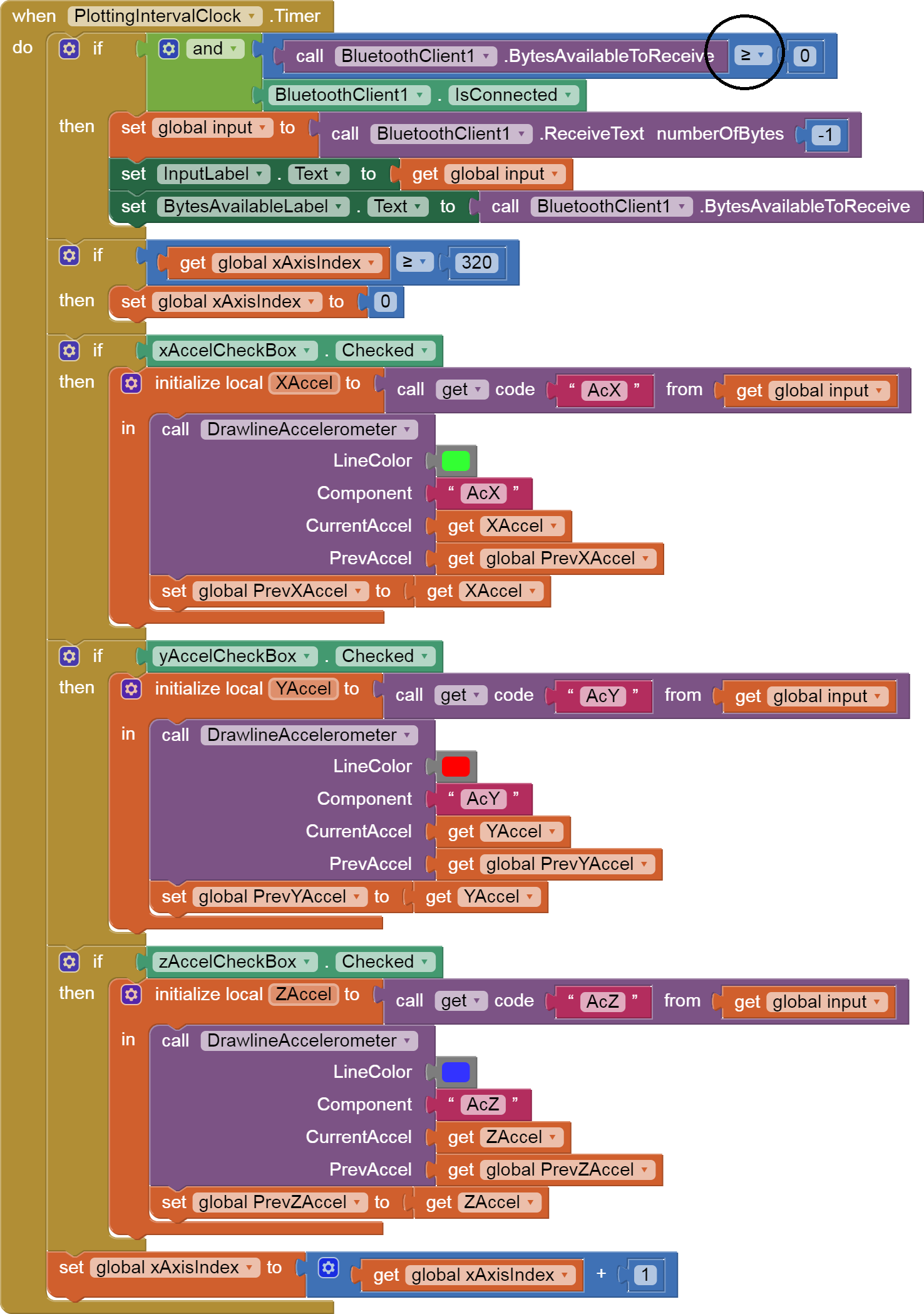
Here are blocks you should change:
P.S. These blocks can be dragged directly into your Blocks Editor workspace.
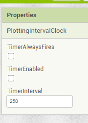
You never started your Clocks.
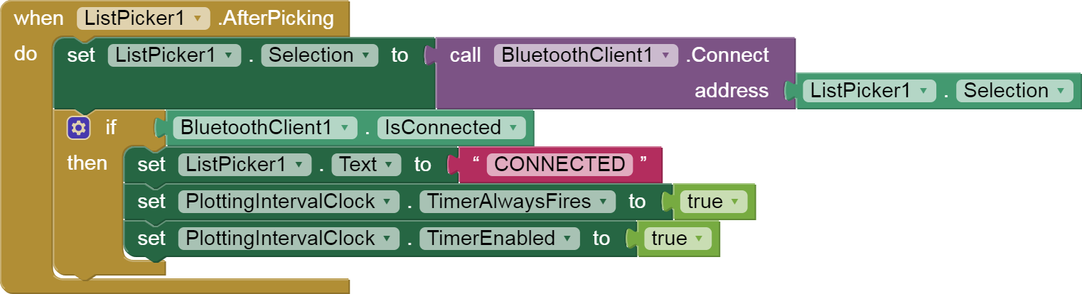
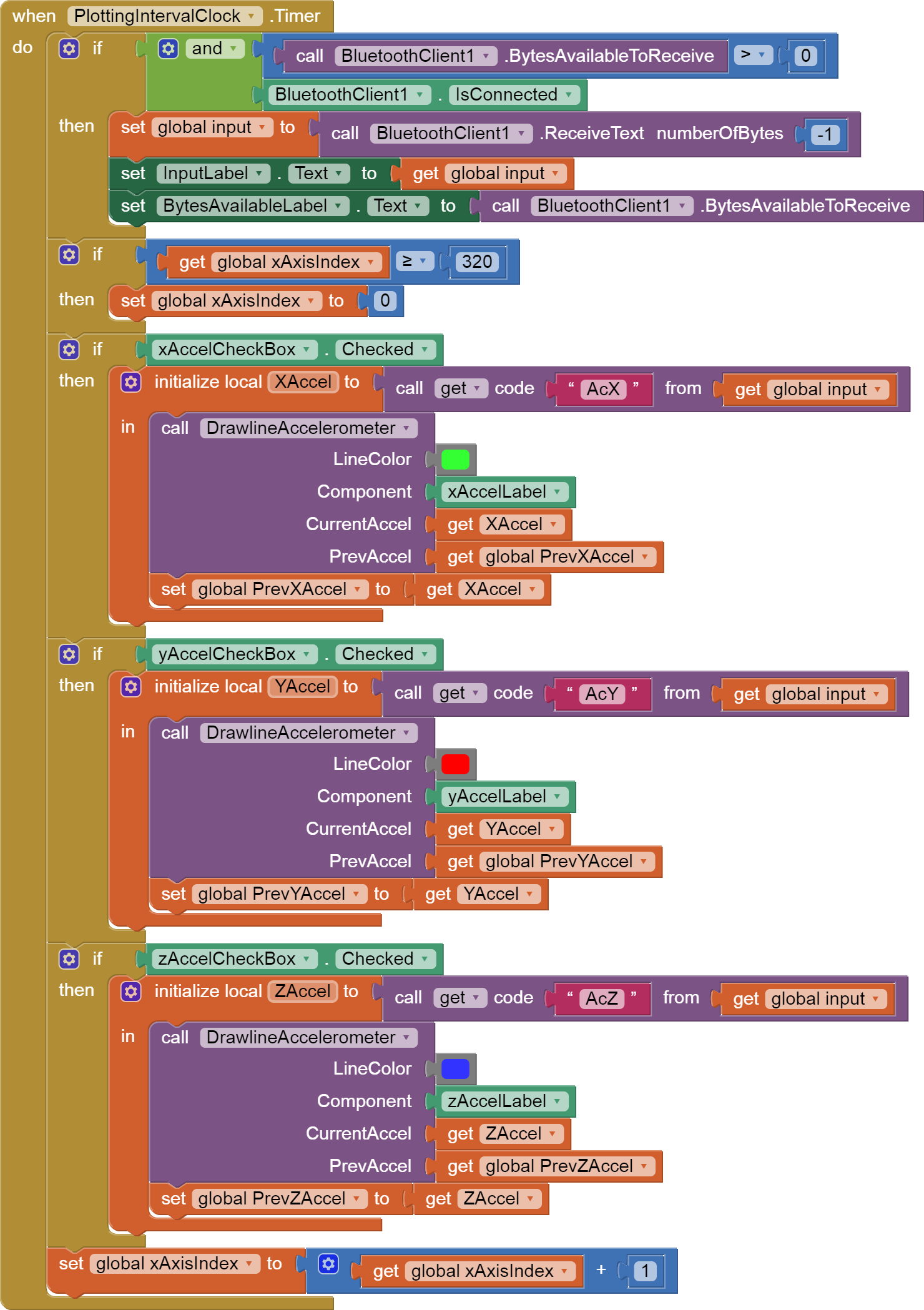
I started the plotting clock at connection time for you.
Your if/then in the plot clock was blocking the input capture under an irrelevant test.
Yea, sure, good to know.
I understand, I changed everything as you added in the screenshots above, but still something is wrong. At this point, after connecting bluetooth with ESP32, the entire application screen does not work (i.e. wherever I click, nothing changes - back button, checkboxes, whatever).
What else are we missing? What do you think?
The >= allows empty text into the input stream.
You don't want that.
Use > 0 instead, like in my blocks.
Sorry for late reply, but it was the weekend.
I have changed the sign as you wrote above, but there is still something wrong and an error pops up after connecting to bluetooth to ESP32.
In the link above, I am sending you a recording from the phone.
Maybe the problem is that i have two Clocks or didin"t "initialize global CurrentAccel". Hmmmm
You sent a pieve of text into a socket expecting a label component, 3 times
See attached correction.
P.S. These blocks can be dragged directly into your Blocks Editor workspace.
Okey, I changed as in your attached pictures but unfortunately the same error still occurs as I posted above.
The application turns on, bluetooth is connected to ESP32 and it looks like the error was somewhere when turning on the readings, because without the checkboxes enabled, the error does not pop up, but after turning on any checkbox, the error shows again.
I try different possibilities myself, but I still can't figure out what else to change and I back to your recent suggestions for the app.
In the attachment I am adding the file "aia" after the last changes.
Sorry for the further spam, but I really want to finish the project.
Acce.aia (13.3 KB)
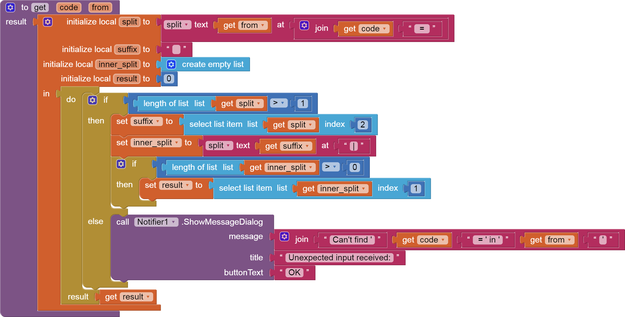
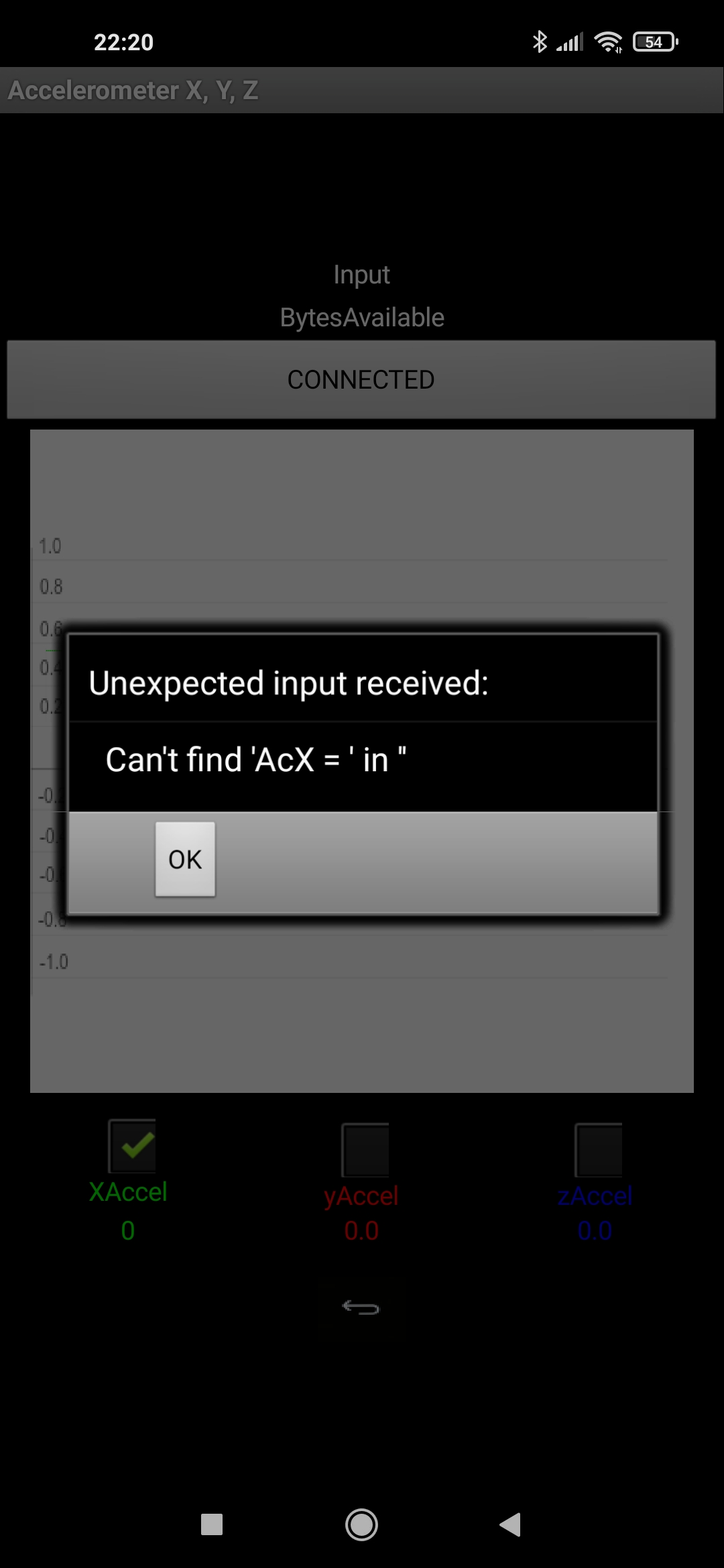
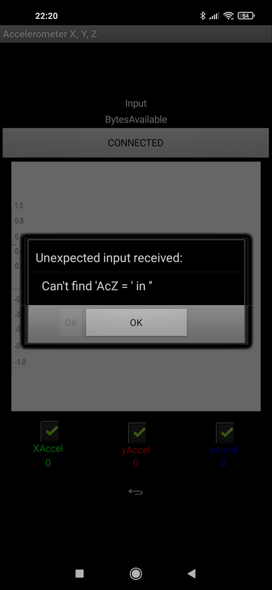
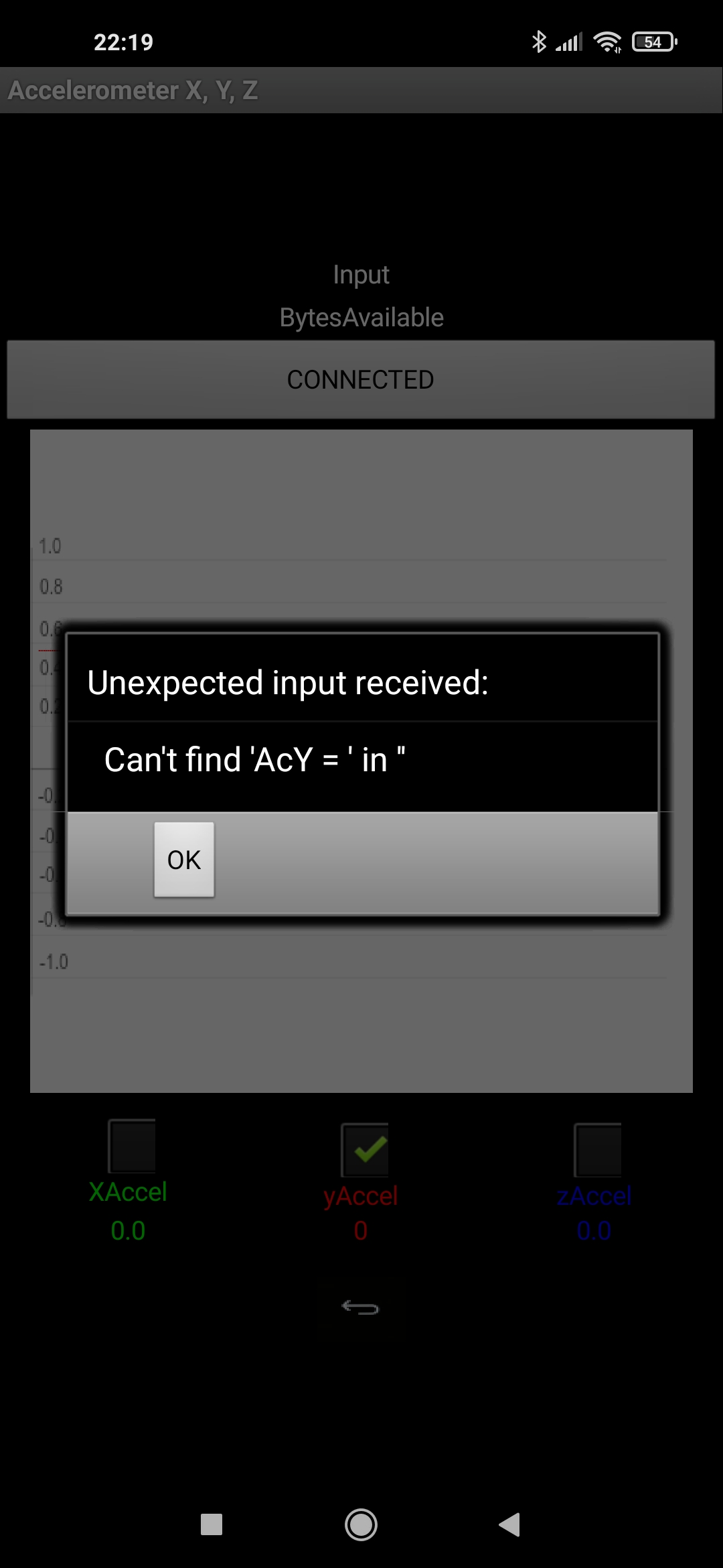
Since your error is in list processing against a split of the input, you were in need of extra code to check if the splits worked before doing list selects.
Add a Notifier1 to your Design screen, and pull in this enhanced procedure.
Upload the error message here if it is not obvious.
P.S. These blocks can be dragged directly into your Blocks Editor workspace.
Hello again ,
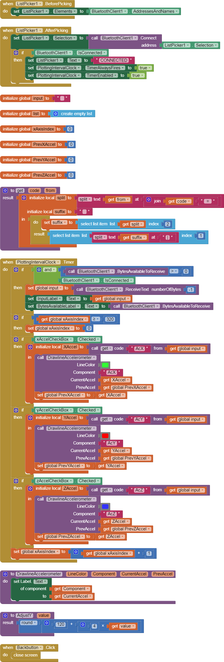
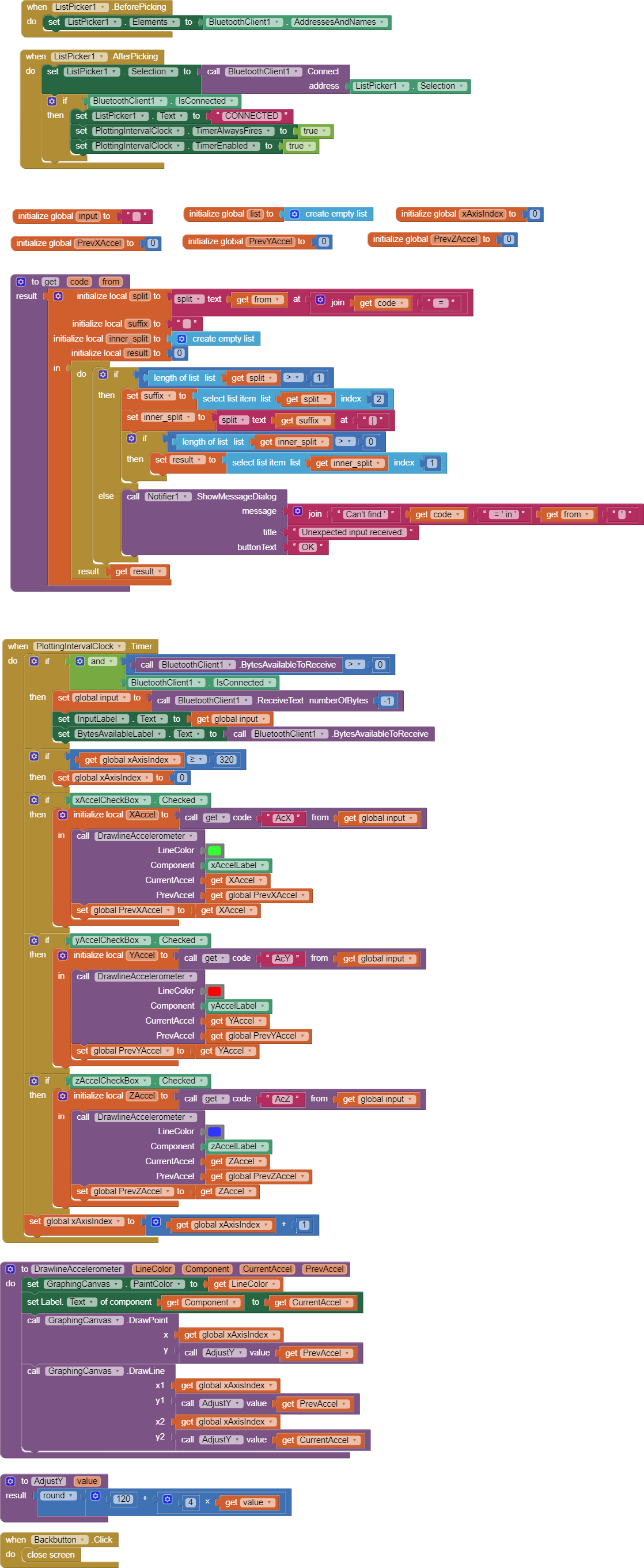
I did what you suggested. There are my all blocks and screenshots from my phone.
I don't know what i have to change 
I am not convinced you are receiving any data over BlueTooth.
Either that, or your BlueTooth input stream included a test announcement from you that it was starting up.
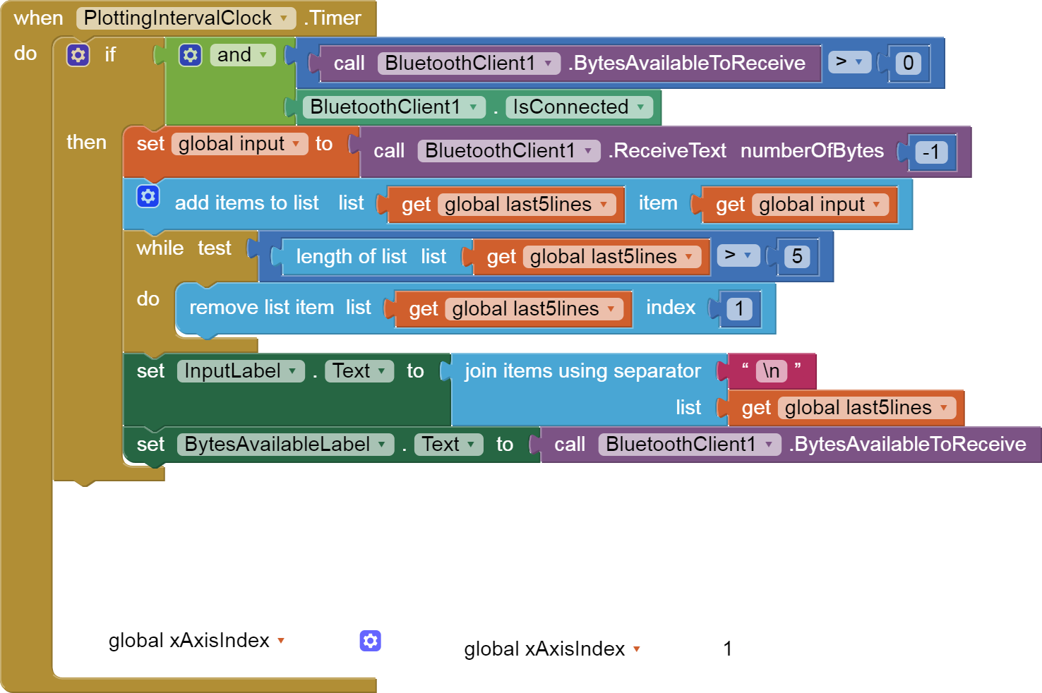
In your Clock Timer that asks for and processes messages, instead of
processing each message, JOIN it to a Label.Text and show us the results.
You might need the help of a hardware guy on this.
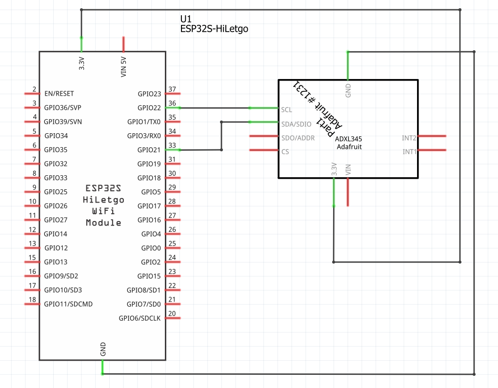
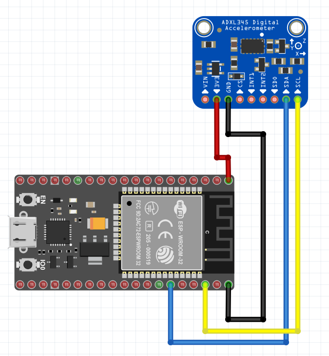
Prepare to upload a wiring diagram.
Hmmm, i do not know what you mean to "JOIN" to Label.Text.
Sorry, like i said im still learning.
You wrote about wiring diagram so in the attachments i send two schemes showing how everything is connected. It's a simple layout. Of course, the cable from ESP32 is connected to the USB of the laptop.
Let's go all the way back to your first post, with your Arduino code.
You have 3 components you talk to for I/O:
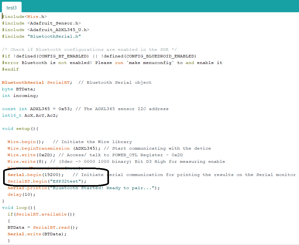
I see you printing to Serial, but not to SerialBT.
Coincidentally, the program image you posted with a data stream is titled COM4, which sounds like a PC port name. You have print commands in your sketch to send to Serial, but not to SerialBT.
The name SerialBT has BT in it, so I am going to guess that's the port you should be printing to in order to get it to go out on BlueTooth.
Could it be as simple as this?
P.S. Here are some draggable blocks to just show the input stream, without trying to plot it.
They should validate my hypothesis.
By The Way, I am confused by the different ways you begin serial transmission for Serial and SerialBT. For one of them, you set a bps rate number, and for the other you pass it a piece of text? See attached.
Sorry for not responding but I was on vacation.
After the last message, I understood the mistake I had made. After changing the code in arduino, the application started to record vibrations in the axes, so everything was fine  . Only the thickness of the line (green, red and blue) is a bit thin and not very visible. Is there any easy way to change this?
One more question, do you know if it is possible to switch two sensors on one screen? I mean adding a second sensor and creating two buttons at the bottom of the phone screen that allow you to change them, for example "sensor1" and "sensor2" and depending on which I click, it would show the readings. Will it be difficult?
Because from what I read on the internet, adding another screen in the application and turning on a second sensor there, I would have to connect to bluetooth again, which would be very inconvenient.

See the code I posted earlier for keeping the last 5 lines of data received.
Imagine you had a way to separate out the two sensor readings from each incoming message.
Keep a separate global list for each sensor's readings, with a limit (100?) on how many readings to keep in each sensor's list.
When you click a button to graph a sensor, clear the graph canvas (optional) , change your color, and run down the appropriate list graphing the readings.